Technical paper · Consumable selection · August 2026
You don’t need a different process. You need a different size.
Solid, flux cored and metal cored, compared properly, and why 1.0 mm solid wire is the pick for most of what a fab shop welds.
A sales rep puts two spools on your bench. Same 1.2 mm on both. Runs the solid wire at 250 amps, runs the flux cored at 250 amps, and the flux cored eats wire noticeably faster.
They are not cheating. That happens.
What they don’t tell you is why, and the why is what this article is about. It has nothing to do with the flux being clever or magic. It has everything to do with the hole in the middle of the wire. The intent is after reading this we can dispel some of the myths you base your decisions on.
Once you understand the mechanism of increased deposition rate, you stop reaching for a different type of wire and start reaching for a different size. And the wire I’d have in most machines in most shops isn’t the 1.2 mm everybody defaults to because their logic tells them its faster. It’s 1.0 mm solid.
Three consumables, and I’ll use the ISO 4063 numbers because it saves an argument later:
- 135 MAG – GMAW with solid wire electrode. ER70S-6.
- 136 MAG – FCAW-GS with flux cored electrode. E71T-1.
- 138 MAG – MCAW with metal cored electrode. E70C-6M.
Same strength classification. Three completely different animals.
The power band analogy
If you’ve ridden a two stroke dirt bike or driven a turbo car this should make sense.
A two stroke off the pipe is gutless and bogs down. Same bike, same fuel, same rider. Get it into the power band and it comes alive. A turbo below boost is just a small motor with lag. Keep it in the ‘zone’ and it pushes you back in the seat.
Welding wire is identical, and the power band / turbo zone is current density. Amps divided by the area of steel actually carrying them.
Burn-off in any wire process has two parts. There’s arc heating at the tip, which scales with current. And there’s resistive heating of the stickout, which scales with the current squared divided by the conducting area. That second term is where all the action is, and it’s the one the sales reps never mention.
Here’s the bit that matters. A solid wire carries current through the whole of itself. A cored wire carries it down the steel sheath around the outside, because a compacted powder core has too much contact resistance to be worth anything as a conductor. So the conducting area of a cored wire is not the area on the drum label. It’s the area of the sheath.
Run the geometry on all four:
| Wire | Total area | Core, by volume | Conducting area | A/mm² at 250 A |
|---|---|---|---|---|
| 1.2 mm GMAW, 135 | 1.13 mm² | 0% | 1.13 mm² | 221 |
| 1.2 mm MCAW, 138 | 1.13 mm² | 21% | 0.89 mm² | 281 |
| 1.0 mm GMAW, 135 | 0.79 mm² | 0% | 0.79 mm² | 318 |
| 1.2 mm FCAW, 136 | 1.13 mm² | 38% | 0.70 mm² | 357 |
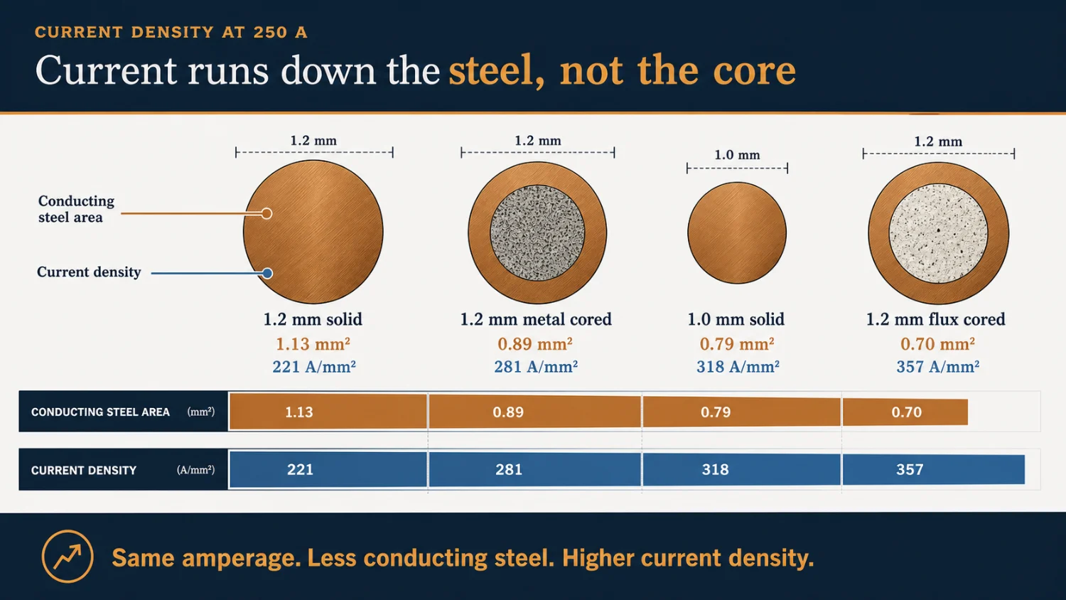
Calculated from wire geometry at published fill factors, 18% flux and 15% metal powder by weight. Core densities are assumptions, not published values, so treat the exact multiplier as indicative and the ranking as solid.
Look where the 1.0 mm solid wire sits. Not at the lower end of the deposition rate range with its 1.2 mm cousin. Up in the middle of the cored wires, past the metal cored, close behind the flux cored.
That’s the whole concept on one line.
The 1.2 mm solid wire isn’t slower because it’s solid. It’s slower because at 250 amps it’s off the pipe, out of the turbo sweet spot.
What that diameter does to the burn-off
Numbers, because the geometry argument is only worth something if it is explained in kilos.
| Amps | 1.2 mm solid | 1.0 mm solid | 1.2 mm flux cored | 1.2 mm metal cored |
|---|---|---|---|---|
| 200 A | 2.3 kg/h | 2.6 kg/h | 2.3 kg/h | 2.7 kg/h |
| 220 A | 2.6 | 3.0 | 2.6 | 3.2 |
| 250 A | 3.1 | 3.5 | 3.2 | 3.9 |
| 280 A | 3.6 | 4.1 | 4.0 | 4.6 |
| 300 A | 3.9 | 4.5 | 4.6 | 5.1 |
Deposited kg/h. Flux cored is Lincoln’s published table for 0.045 in Outershield 71M in CO₂, with its own measured efficiency column. Metal cored is Hobart’s published table for 0.045 in Metal-Cor 6. The two solid wire columns are calculated, fitted to Lincoln’s published spray figures for 0.9 mm L-56 and checked against their published 1.2 mm short arc figures, which it hits within 10%. Roughly 16 mm stickout.
Read the 250 amp row, because it’s where most people spend their time.
Drop from 1.2 mm solid to 1.0 mm solid and you go from 3.1 to 3.5 kg/h. You didn’t change process. You didn’t buy anything dearer. You changed the diameter and expected it to go slower, because in your mind 1mm is smaller than 1.2mm.
Thirteen per cent more weld metal at the same amps, and it puts you past the flux cored.
Look what that puts you next to. At 250 amps that 1.0 mm solid wire is now depositing more than the 1.2 mm flux cored is. The wire the rep sold you at a premium as the productive one.
Here’s the same fact from another perspective, which is the one I prefer because there’s no modelling in it at all. Just kg of what lands in the joint as weld versus per metre of wire burnt:
| Wire | Wire mass | Recovery | Deposited |
|---|---|---|---|
| 1.0 mm solid | 6.17 g/m | 96% | 5.92 g/m |
| 1.2 mm flux cored | 6.71 g/m | 85% | 5.70 g/m |
Near enough to identical. A metre of 1.0 mm solid wire and a metre of 1.2 mm flux cored put the same steel in the joint. One of them costs a good deal more per kilogram than the other, and one of them leaves you a heap of slag to chip off.
Not all cored wire works that way, MCAW is full of metal powder it goes the other way. Metal cored still wins on deposition at the same amps, and it isn’t close. 3.9 against 3.5 at 250 A. Its throwing metal powder into the joint, not flux that converts to slag. That’s a real advantage, but it comes at a cost and needs to be balanced in its application.
Why 1.0 mm and not 0.9 mm
Fair question, because 0.9 mm has a higher current density again.
Three reasons. Habit, metal per metre, and range.
We use a lot more 0.9 mm than 1mm out of habit and its the cards we were dealt. Its what we have always done, primarily a hang over from the pre metric period and maintained by the yanks and their equipment. The keys players be it red or blue optimise the setups on 0.9 mm and 1.2 mm. The default drive rolls in the wire feeders are usually these sizes. We have just followed and no one really stopped to question it. Previously 1mm was significantly more expensive due to lack of volume coming into the country. Now’s the time to “check your thinking”, there are real gains to be had.
Conversely European and Asian machines are optimised around 0.8 mm, 1 mm and 1.2 mm as they are true metric sizes.
The 0.9 mm carries 4.99 g/m against the 1.0 mm’s 6.17. That’s 19% less steel per metre of wire fed, so to match the deposition you’re feeding it a lot harder, and everything downstream of the drive rolls feels it. Liner condition, tip life, burnback margin, feedability round a bend in the torch. A 0.9 mm wire run hard is a wire that finds every fault in your consumables, rips your tips out and workshops with tired gear / torches will hate you for it.
Range is the bigger one. Cigweld publish 1.0 mm Autocraft LW1-6 at 100 to 280 amps, 16 to 29 volts, 3.5 to 15 m/min. 1mm just has a more useable range. You can put 5 mm sheet metal work through the bottom of it and an 8 mm fillet through the top without touching the spool. The 0.9 mm tops out earlier and you’ll be swapping. The 8mm fillet in a single pass is where you will see the real difference, 0.9mm runs out of legs at about that point.
One practical note for anyone reading a US datasheet and getting confused. 1.0 mm is largely an Australian, European and Asian size. Cigweld publish a full 1.0 mm row. Hyundai publish 1.0 mm test conditions. Lincoln, Hobart and Select-Arc skip 0.040 in entirely and jump from 0.035 to 0.045. So if you go looking for American data on it you won’t find much, and that absence is about their measurement system, not about the wire.
Where 1.0 mm stops being the answer: heavy multi-run work on 20 mm and up, where you want the ceiling. That’s 1.2 mm properly in spray, or 1.6 mm if you’ve got the machine for it, and nothing in a 1.2 mm cored wire gets within a bull’s roar of 1.6 mm solid at 12 m/min. That said people in the next suburb will be getting ray burn. More steel in the cross section and none of it going to the floor. But you just have to be willing to put the amps through it and hold on to the torch.
The fifteen per cent you sweep up
Buy a 15 kg spool of flux cored. Before you strike an arc, put two and a bit kilos of it in the bin.
That’s roughly what happens and it isn’t a rort. The flux is doing real work. But it’s mass you paid for at flux cored prices that never becomes weld metal, and the unrecognised loss under the manipulator or bench at the end of the shift is only the visible part of it. Spatter and fume take their share too, so it isn’t all slag.
Published recovery figures, all of them:
| Source | Figure |
|---|---|
| Lincoln, Outershield 71M, per-row measured | 83 to 85% |
| Hobart | “falls into the 82 to 85 percent range” |
| The Fabricator, Meyer and Koltz | “FCAW averages about 87%” |
| Solid wire and metal cored, same sources | 92 to 98% |
Call it 85% for flux cored and you’re at the top of what Lincoln and Hobart publish and below what The Fabricator quotes. That’s a justifiable working number, and I’ll use it, but know that it’s a working number and not a measurement of ‘your shop’.
So run it out over a job:
| Wire | Purchased per 1000 kg deposited |
|---|---|
| Solid, 96% | 1042 kg |
| Metal cored, 95% | 1053 kg |
| Flux cored, 85% | 1176 kg |
On a job needing a ton of deposited weld metal, flux cored has you buying about 135 kg (9 spools) more consumable than solid wire, at a higher price per kilogram, to put the same steel in the same joints. Before you’ve paid anyone to chip it off, and before you’ve paid for the arc-off time they spent doing it.
That’s the ‘productivity number’, and it doesn’t once appear in a FCAW deposition rate table the sales rep showed you.
The flux cored premium, like for like
Start with the cost per Kg price. These 1.2 mm pairs compare solid and gas-shielded flux cored wire within the same retailer and on one GST basis. They are a retail snapshot, not a standing market claim, but the multiples hold true from my experience.
| Retailer / brand | Solid | Flux cored | Sticker premium |
|---|---|---|---|
| Bob The Welder / Bossweld | $73.00 | $96.00 | 1.32 times |
| Welding Supply / Hyundai | $57.90 | $94.80 | 1.64 times |
| Gentronics / Cigweld | $55.29 | $65.71 | 1.19 times |
| Gentronics / Topgun | $39.60 | $63.99 | 1.62 times |
| Gentronics / Lincoln | $100.87 | $160.38 | 1.59 times |
On the shelf, the flux cored premium is therefore roughly 1.2 to 1.6 times in this sample.
Now correct it for recovery. Cost per kilogram deposited = purchase price per kilogram divided by deposition efficiency. Solid GMAW commonly runs about 93 to 98% deposition efficiency; gas-shielded E71T-1 sits around 82 to 88% once slag, spatter and fume are accounted for. Recovery alone therefore widens the flux cored-to-solid ratio by roughly another 6 to 20%.
On representative mid-range values, the Bossweld comparison moves from 1.32 times at the shelf to about 1.48 times per kilogram deposited, and Hyundai from 1.64 to about 1.83 times. The exact answer moves with the efficiency you can actually measure, but it never moves in flux cored’s favour.
Then add deslagging. On multi-run work the slag has to be removed, the toes exposed and the pass inspected before the next run goes over it. That is paid non arc-on time repeated between passes, plus the access, tools, clean-up and inclusion risk that come with it. This is where flux cored can become genuinely expensive even when its machine deposition rate looks strong.
That does not make flux cored the wrong choice. If the slag lets you weld vertically at a current solid wire cannot hold, or avoids lack of fusion and rework, it can still be the cheaper joint. In the vertical position and a few other specific applications it is absolutely my first choice. Just compare total cost per acceptable kilogram in the joint – wire, recovery, labour and rework – not dollars per spool or the headline deposition rate the sales rep gave you.
So what is the slag actually for
None of the above makes flux cored a bad process. It’s an excellent process, grew up using it and used the old school ‘wooden spool dual shield’, strangely I love the smell. The purpose of this paper is to highlight the BS and the fact it’s just sold on the wrong claim in many cases.
So where FCAW does stand out, pour a concrete wall and you need form work, or the wet mix runs down the road and you’ve got a footpath instead of a wall. Flux cored has the form work built into the wire. The slag freezes fast and holds the pool on the wall while it sets. You can get it to look like glass with the right settings, nothing comes close.
ESAB put it as well as anyone: “the fast-freezing slag holds the weld pool in position in all orientations, giving the operator greater control and reducing the skill required for positional welding.” And elsewhere, “the slag system from the core supports out-of-position welding by controlling weld pool fluidity.”
But this is the sentence that needs to form part of the argument, also ESAB: “in out-of-position work, flux-cored electrodes can operate at higher currents than solid MIG in short-circuit mode, improving sidewall fusion and reducing the risk of lack-of-fusion defects.”
Read it twice.
The point
You are not buying a wire with magic deposition or fusion properties. You are buying the ability to use higher amps vertically.
Solid wire out of position on conventional gear has to come down out of globular / spray, because spray is a downhand mode because its too fluid and the weld pool has no support. You have to pull back to short arc to manage the weld pool fluidity, stop weld face convexity and in the process your deposition rate collapses and you’re in the transfer mode where lack of fusion reigns supreme. Flux cored doesn’t have to drop that far. That’s the advantage, it’s a big one, and on a vertical joint it beats solid wire on deposition outright, everyday of the week.
Its worth knowing there’s a number behind the quality side too. When somebody counted lack of fusion at weld toes across four consumables, in position, solid wire had a 35% reject rate and a rutile flux cored at 1.9%.
One thing to get clear in your head: FCAW is not FCAW, rutile and basic wires are not the same. EWI: “the solidifying slag of the basic flux wires provides less support for the weld pool making basic flux wires less operable in out-of-position welding.” Your all-positional shop wire is rutile, a T1. Treating “flux cored” as one category will mislead you. T5, basic is a different animal, typically runs like a pig versus the T1.
The same wire downhand is a different beast
Here’s where flux cored catches people out, and nobody warns them.
The metal in a rutile flux cored deposit is more fluid than solid wire, not less. It’s a high oxygen deposit and oxygen thins it out. What makes it behave on a wall is the slag skinning over the top of it, like the skin on a cup of tea holding the tea still.
Lay the joint flat and that skin isn’t doing much for you any more. What you’ve got left is a runnier pool than you’re used to.
So a 2F (PB), downhand fillet with flux cored is a different technique, not the same technique vertical lying down. Travel too slow in a fillet weld and the pool slumps and wants to over roll on you, 6mm fillet is ok, but push to 8mm and it wants to rip out the top edge and give you a lumpy bottom toe.
Four things to hand your leading hand:
- It’s a cored wire, set you machine up properly, knurled rolls, light drive roll pressure and 1.2H tips.
- Set travel speed so the puddle ‘mass’ does not get too great, that gravity takes over and it overrolls.
- Its got slag, you drag. Drag angle 15 to 25 degrees flat and horizontal, Push angle 5 to 10 vertical up. Welders routinely run far too much drag in the downhand because it feels productive and there are times where it is appropriate.
- Keep the weave off it for downhand fillets as a rule. Save it for the vertical, where it works.
That’s the honest picture. Awesome for vertical up. Needs respect in the downhand or you will make a mess. You can not take someone that is used to solid wire and throw them FCAW and expect them to produce the same result without some training. Same equipment, different weld pool characteristics.
Roots and back gouges
This is where I part company with the brochures, and I want to be careful about how I argue it, because the published material doesn’t say what I’m about to say.
Hobart publish that gas shielded flux cored wires “provide high arc force, which greatly assists penetration into the base material”, and that they “ensure complete root fusion in limited-access joints.” That’s their position and it’s the opposite of the folklore.
Here’s my problem with settling it on penetration either way: nobody has measured it. There is no published macro study comparing 135 spray, 136 rutile and 138 at matched current, same gas, same diameter, sectioned and etched. There are no arc pressure comparisons either, because a consumable electrode throws droplets that wreck the instrumentation. Both the marketing claim and the counter-claim are unmeasured.
So don’t argue the root on penetration. Argue it on where the slag has to go, which can not be disputed. In a fillet and in a joint with backing the slag needs somewhere to form, this typically displaces the weld metal. Its why so many welders fail single run fillet WQT with FCAW.
FCAW has too fluid a weld pool for an open root in the main. I am not saying it can not be done, but I am saying its typically not repeatable from my experience. MCAW can be used for open roots and have seen a number of examples where its worked, I am yet to be convinced for any application it is better than solid wire when putting in a root.
The evidence for that argument is what the industry does rather than what it says:
- AWS D10.11M/D10.11:2007, the guide for root pass welding of pipe without backing, has no FCAW or MCAW open root procedure in it. Nineteen years and nobody’s added one. It’s a guide, not a code, so treat that as evidence of practice rather than a prohibition.
- Lincoln patented a metal cored electrode for open root welding, US 7,397,015. What did they have to do to make a cored wire work in an open root? Strip the flux out, down to under 1 to 2 per cent slag forming agents, and run it on a controlled short circuit waveform. Their stated benefit is a root bead with “little or no slag on the upper surface.” When the fix for putting a cored wire in an open root is removing the core, that’s close enough to an endorsement of the point.
- The exception proves the boundary. Put a steel or ceramic backing behind the joint and the whole argument shifts to a degree. The pool fluidity is not so much of an issue anymore, the profile is moulded rather than left to gravity, and flux cored onto ceramic backing is completely standard structural practice for single sided butts in deck plate and box sections. The concavity argument is about open roots, not all roots.
For an open root on conventional gear: solid wire, and if you’ve got a modified short arc waveform on the machine, use it. That’s what the chopper technology of STT, RMD, LSC etc were built for. Miller’s own target for a good root, worth knowing because people get it wrong in the other direction, is that “the face of a good root weld appears flat (neither concave or convex)” with about 1.6 mm of reinforcement on the back. Flush, not proud. Excessive convexity is its own defect.
And a concave root is a real problem, not a cosmetic one. It removes throat, so the same shrinkage load acts on less section. The weld face is already under tension and there is no extra metal to pull on as the joint contracts. It often leaves a surface notch / shrinkage groove. And it sits the last metal to freeze, the most segregated, the highest concentration of manganese sulphides and the weakest, right at that notch. Troubleshooting for it is two lines. Condition is: “the surface of the weld is concave.” Solution: “make sure the bead surface is ‘slightly’ convex.”
Metal cored, and what to watch
Metal cored is a genuinely excellent process and the deposition is not just marketing. 3.9 kg/h at 250 amps against 3.5 for the best solid wire in this comparison. It produces beautiful welds, at a high deposition rate with low spatter if you know what you are doing. Almost no slag, just a few silicate islands you flick off. Minimal spatter, good gap bridging, high travel speeds, and it loves a moggie (weld tractor), boom or a cobot / robot. For downhand production fillet welding on a tractor I’d put it in front of both GMAW and FCAW almost every time.
The part nobody selling it will tell you, and they should ‘it’s a greater risk of cracking’, both crater and solidification. This next bit is my position from experience of burning wire, client feedback and cutting macros, not a published finding.
What’s published: Hobart, Barhorst, Hensley and Guy all describe metal cored as giving “a broad, cone-shaped arc and a wide penetration profile”, wider than the finger-like penetration of solid wire. Hobart also brackets it with solid wire on cracking: “very narrow, deep joints on thicker materials increase crack sensitivity, whether using solid wire or metal-cored wire.” And I searched hard for anything linking metal cored specifically to crater or solidification cracking. There isn’t any, not surprisingly. Not in AWS, Hobart, Lincoln, Miller, ESAB or the journals.
What I cut on a bandsaw off a metal cored fillet in spray transfer is a broad face with a deep central finger under it. It rips in. Which is actually both of the manufacturers’ descriptions at once, and it’s the combination that causes the trouble. What matters for cracking is not how wide the bead looks at the surface. It’s the local depth to width ratio through the finger.
TWI’s threshold, verbatim: “as a general rule, weld beads whose depth to width ratio exceeds 2:1 will be prone to solidification cracking.” They also give a floor, 0.5:1, because failing to penetrate the root promotes cracking too. Wider is not automatically safer.
Go and cut your own. Bandsaw, etch, ten minutes. Because as established above, nobody has published the comparison and you shouldn’t take my word for it either.
Whatever you conclude about the finger, three things about metal cored are not in dispute and they all push the same way:
Dilution. Deep penetration means a big fraction of the weld metal is remelted parent plate, so the plate’s sulphur, phosphorus and manganese dominate the deposit chemistry. That beautiful all weld metal analysis and mechanicals on the certificate does not highlight a high dilution mechanism and the increased risk of low strength manganese sulphides forming at the centre of a solidifying weld.
Speed. The high travel speeds that make it attractive mean lower heat input per unit length, faster cooling, and a higher strain rate while the weld is solidifying. TWI’s own advice is to avoid high travel speeds at high current because they increase segregation.
Craters. Every time you break the arc you leave one, and it’s the worst spot on the run. It’s concave, so it’s the thinnest bit. It’s the last metal to freeze, so it’s collected everything the run has been pushing ahead of it. And it’s shrinking with nothing left to feed it. A bigger, runnier, faster pool leaves a bigger, deeper crater when you let go of the trigger, and metal cored gives you all three and why it crater cracks far more than FCAW and GMAW if not managed properly.
Think of a river freezing from both banks. Whatever’s floating gets pushed to the middle, and the middle is the last bit to freeze and the first bit to pull apart. That’s centreline solidification cracking in one picture, and a deep narrow bead is a narrow river.
Do not treat crater cracks and longitudinal centreline cracks as two unrelated defects. They are the same feeding problem at different scales. A crater crack is concentrated at the stop, where heat and filler disappear together. A longitudinal centreline solidification crack develops behind the travelling arc when the pool freezes in from both sides and the remaining low strength liquid film cannot feed the transverse contraction as the weld cools.
Metal cored does not invent a new cracking mechanism. The concern is the operating geometry it makes easy: a very fluid pool, high travel speed, high dilution, a concave face and, in the macros I have cut, a deep central finger. The concave weld face removes section while the finger raises the local depth-to-width ratio and being concave means the weld face is already in tension with no extra weld metal to draw on as it shrinks. Both concentrate strain in the last-to-freeze centreline. That bridge from metal-cored behaviour to cracking risk is still my engineering inference, not a published process-specific finding.
The surface can understate it. A broad bead may still hide a narrow central finger, and the first separation can be sub-surface before it opens into a visible line. On critical work, the stop sequence belongs in the WPS: crater fill or downslope where available, run-off tabs where practical, and a defined repair method where a stop cannot be avoided.
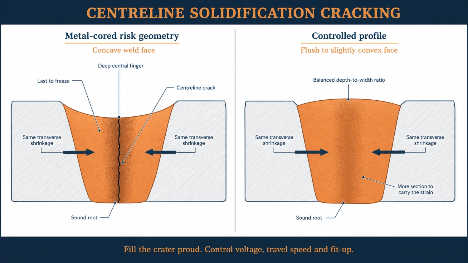
The fix is entirely in your hands, and it isn’t the drum:
- Fill the crater, properly to slightly convex before you break the arc. Not concave. Proud.
- Use the crater fill or current downslope if the machine has it. Run off tabs on butts.
- Train the team on the different technique to stop. Stop watch the colour go out of it, hit it again.
- Watch the volts. High voltage increases the concavity of the bead, low voltage increases the punch / depth of penetration too much.
- Control the fit-up. Deep narrow anything, you’re asking for trouble.
None of that makes metal cored unsafe. It makes it a process whose bead geometry has to be controlled deliberately rather than accepted as whatever the arc gives you, it comes down to training.
If you own a pulse machine
Everything above assumes conventional constant voltage gear, because that’s what most shops have got. Waveform control changes three things and it’s worth knowing which three.
Solid wire goes vertical up much better, with a reduced risk of lack of fusion. Pulsed gives you improved all-positional capability at mean currents of 50 to 150 A, in a mode that isn’t dip transfer. That’s the genuine mitigation for lack of fusion, and it narrows the flux cored positional advantage substantially. It does not close it. Flux cored still runs at higher current out of position and still has the slag doing the mechanical work. Its still what I would pick FCAW every time, even if the machine has ‘speedup’ or whatever your brand calls it.
Metal cored gets out of position. ESAB are direct about it: to get all-position capability from a metal cored wire, you need short arc or pulse. Without a pulse machine, metal cored does not go up a wall. That’s its scope, not a criticism. I will say, it runs fine in overhead and horizontal, done it plenty of times, you just need to take the edge off the amps.
Open roots become a solved problem. STT, RMD or LSC decouple current from wire feed speed, with some fancy ‘chopper technology’ that makes putting in a root much more user friendly, which is what actually fixed the open root. Not mass per metre, genuine smart technology that provide much better weld pool control. Lincoln’s own words on what conventional CV short arc does in a root: “a flat internal bead, or ‘suck back’ where the bead shrinks back into the root due to high weld puddle temperatures.”
One thing to know before you quote either at a client. Short circuiting GMAW, including the modified waveform versions, is not prequalified under AWS D1.1, AS3992 or AS/NZS 1554.1 on lack of fusion grounds. In D1.1 work those processes need qualification by test. That’s no reason not to use them. Just qualify them properly and don’t get caught assuming.
The decision table
| The job | Wire | Size | Why |
|---|---|---|---|
| General fab, downhand, 3 to 10 mm, mixed work | ER70S-6 solid | 1.0 mm | Best all-round. Sits in the power band at the amps you actually weld at, 100 to 280 A off one spool, best metal recovery, no slag, cheapest consumable. |
| Downhand production fillets, long runs, boom or robot | E70C-6M metal cored | 1.2 mm | Highest deposition at a given current, near solid-wire recovery, high travel speed. Manage the bead shape, the craters and deep penetration |
| Heavy multi-run, 20 mm and up, machine has the amps | ER70S-6 solid | 1.2 | You can crank it, if you can hang on to it |
| Vertical up, conventional CV gear | E71T-1 flux cored | 1.2 mm | The slag lets you use current a solid wire cannot use in that position. Not close |
| Open root, no backing | ER70S-6 solid, modified short circuit if you have it | 0.9 or 1.0mm | Less fluid, greater control and repeatability |
| Root on ceramic or steel backing | Solid | 1 or 1.2 mm | Lower risk of solidification cracking, not as concave profile |
| Pipework rotated or in position | Modified short arc root / FCAW fill and cap | 1 and 1.2 mm | FCAW is way easier and better for rotated, more so for positional |
| Back gouged joints | Solid or metal cored | 1.0 or 1.2 mm | It hits the bottom of the prep much better |
| Mill scale, rust, ordinary fit-up | E71T-1 | 1.2 mm | Deoxidisers in the flux absorb more. |
| High fatigue duty, AS/NZS 1554.5 or upper CC under AS/NZS 5131 | E71T-1 | 1.2 mm | Lower lack of fusion risk, and the failure mode you’re avoiding is fatigue cracks propagating from planar – lack of fusion. |
| Site work in wind | Self shielded, 114 | Not covered here | Different process, different article |
Conclusion – My opinion on what you should use
Solid wire is the best all-round consumable in a fab shop, and 1.0 mm is the sweet spot. Best recovery of the three, no slag to chip, no interpass cleaning beyond a wire brush, cheapest metal in the joint, and at 1.0 mm it runs in its power band at the currents ordinary fabrication actually uses. The problem with solid wire has never been the wire. It’s that most shops leave a 1.2 mm in the machine and weld everything with it, out of the turbo zone, all day, and then conclude solid wire is slow, or it spatter like you wouldn’t believe.
Flux cored is fantastic, and it’s sold to you on the wrong claim. Out of position it’s superb and I specify it regularly. The slag is mechanical formwork for molten steel and there’s no substitute for it on conventional gear. But if a sales rep is selling it to you on higher deposition or deeper penetration, they are misinformed or hoping you are. The deposition advantage is a current density artefact you can buy for free by dropping a wire size still using solid, and the penetration claim was benchmarked against stick welding in the 1950s and has never been re-tested against anything since. From my experience it can not be substantiated.
Buy flux cored for position, surface tolerance, guard against lack of fusion and a wider operating window. Those are real advantages. Just budget for the 15% you sweep up off the floor. Budget for the purchase-price premium and interpass deslagging as well as the 15% that never reaches the joint.
Metal cored is fantastic and it needs managing. Genuinely the highest deposition per amp here, low spatter, near solid-wire recovery, and excellent on a machine-fed downhand fillet. It just runs a fluid pool with no slag holding it, at high travel speed, with high dilution, and it will leave you a concave bead and a nasty crater if you let it or worse an undetected solidification crack at the root that doesn’t get picked up until the NDT the joint. Know that going in, control your volts and your fit-up, fill your craters properly, and it’s a very good wire.
Shifting from GMAW to FCAW or MCAW definitely requires some change management and training of welders. Same equipment different techniques. If I had a shop full of FCAW welders I wouldn’t shift without ‘recalibrating’ the technique of those that are pulling the trigger.
And whatever you conclude off this page, go and measure it. Weigh the spool at the start of the shift, weigh it at the end, time the arc with a stopwatch rather than the shift, weigh the coupon. Look at the slag at the welder feet, get curious as to whats that costing. Do that once for each wire you run and every number on this page becomes irrelevant, which is exactly the point of publishing them.
The only number that counts
The only deposition rate that matters and is credible is the one measured in your shop, on your joints, by your welders. Taking into account all of the factors
What’s verified, what’s derived, what’s mine
Nobody in this industry does this part and it’s the reason these pages get quoted, so here it is.
Published, quotable, checked. Cigweld’s 1.0 mm current range and wire feed speed. Lincoln’s transition current table and their per-row measured efficiency column on Outershield 71M. Hobart’s Metal-Cor 6 and Excel-Arc 71 deposition tables. Hobart’s and Lincoln’s efficiency figures. The ESAB slag quotes. The EWM travel speed and weaving guidance. Bernard’s drag angles, which come from FCAW guidance generally, some of it self shielded. TWI’s 2:1 and 0.5:1 depth to width thresholds. The Lopez Martinez and Korsgren 1993 cold lap counts. AWS D10.11M/D10.11:2007 and Lincoln patent US 7,397,015. ISO 5817, API 1104 cl 9.3.6 and ASME VIII Div 1 UW-35(e).
Calculated by me, from published inputs. Every current density figure, from wire geometry and published fill factors. The two solid wire deposition columns, fitted to Lincoln’s published 0.9 mm spray data and validated against their published 1.2 mm short arc figures. Deposited grams per metre and wire purchased per tonne. The retail sticker comparisons use the price snapshot supplied for this revision; the deposited-metal multipliers apply the stated efficiency ranges to those prices.
Assumptions you should know about. Flux core density 2.8 g/cm³ and metal core 5.0 g/cm³. Fill ratios are published, core densities aren’t. Push the flux core to 3.5 and its current density drops from 357 to about 330, so the ranking holds and the multiplier moves. Treating the core as a perfect insulator slightly overstates the effect, because flux cores carry iron powder and metallic deoxidisers that take some current. Deposition efficiency of 85% for flux cored, 96% solid, 95% metal cored. Stickout around 16 mm. Retail prices move and product pack sizes differ, so re-normalise every comparison to dollars per kilogram, confirm the GST basis, and re-check the exact classifications before purchasing.
Not published anywhere, and I looked for it. A spray transition current for 1.0 mm solid wire. Any manufacturer deposition chart for 1.0 mm solid. Any macro study comparing penetration across 135, 136 and 138 at matched current. Any source linking metal cored specifically to crater or solidification cracking. Any stated wire feed speed ceiling for 1.0 mm solid.
My position, not a published finding. The broad face with a deep central finger on metal cored fillets in spray, and the cracking risk that follows from it. The slag-in-the-root argument as the reason to keep cored wires out of open roots and back gouges, as distinct from a penetration argument. Back stepping into the bead before breaking the arc.
What this page does not do
And what this page does not do. It doesn’t qualify anything. Consumable and process selection on any coded, pressure or structural job is the welding coordinator’s call against the standard, and it needs signing off by whoever carries the responsibility for it. Use this to have a better argument, not to skip one.
The one page version
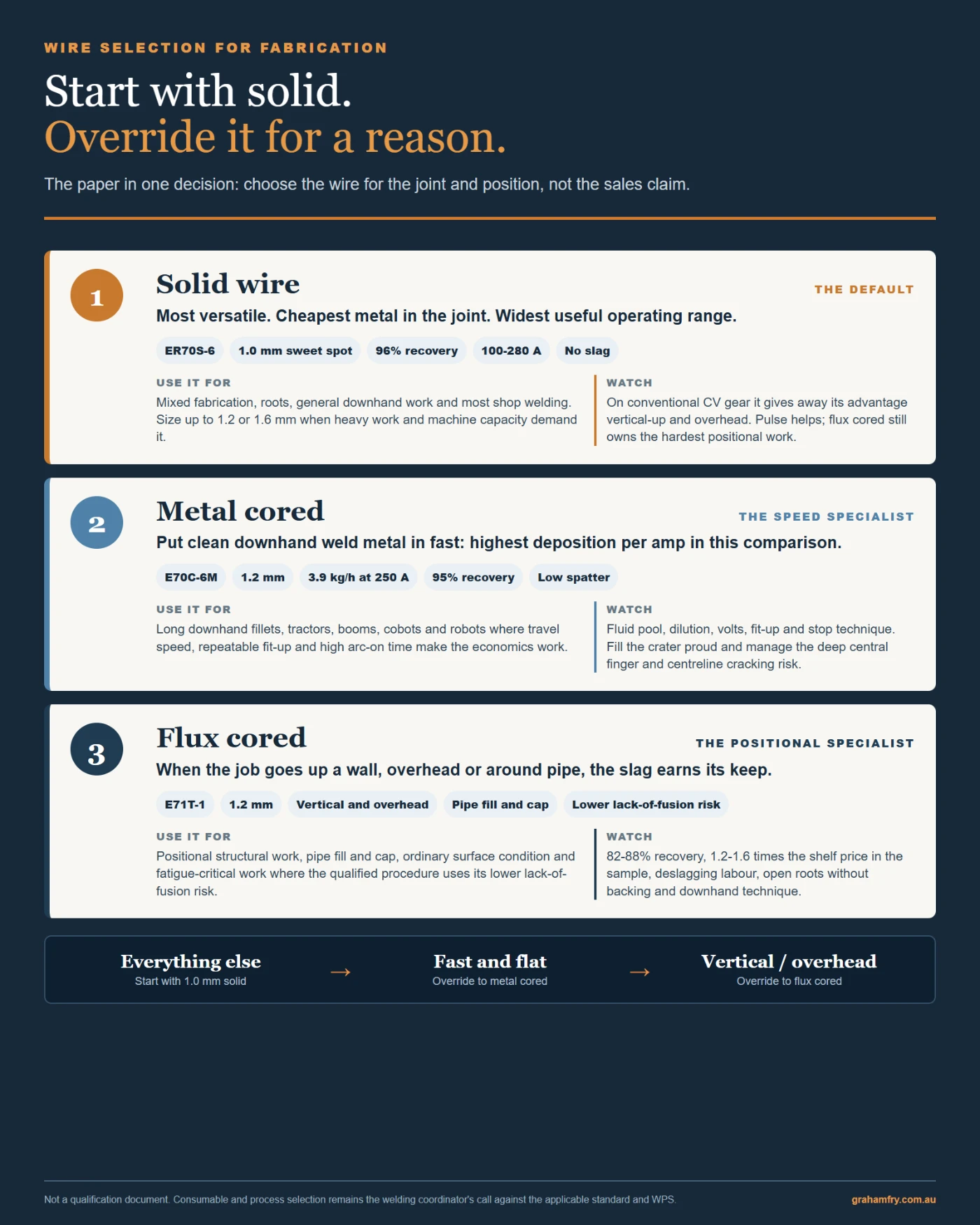
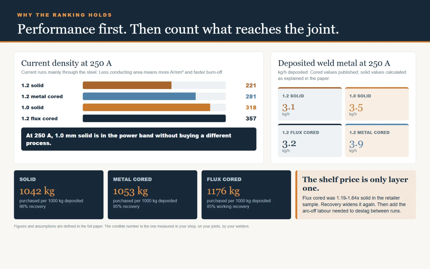
Print this one and put it on the wall by the wire store.

Graham Fry
Welder and International Welding Engineer. Principal Welding Engineer at Technoweld, working across AS/NZS 1554, AS/NZS 5131, AS 3992, AS 1210, ISO 3834, ASME BPVC and ASME B31.3 on procedure development, welder qualification, fabrication compliance and failure investigation.
Disclosed interest. Graham is a director of Technoweld Pty Ltd, which sells welding consulting, procedure development and training. He does not sell welding consumables and holds no distribution or supply arrangement with any consumable manufacturer named on this page.