Technical resource
Synergic MIG: what the machine is really doing, and why trim is not a heat knob
Synergic control is not the machine setting everything, it is not some magical function, it is not pulse, and it is not controlling your arc. It is a library of settings held in the machine’s memory: a relationship between amps and volts, built from three inputs, wire type, wire size and shielding gas, that somebody measured once to create a synergic line. You set the amps and you trim the volts. Trim is the quarter turn you give it when the job in front of you is not the job the curve was measured on.
Synergic decides what the machine asks for. Your hand decides what the arc gets.
Four different people misunderstand synergic welding in four different ways, and I’ve had all four conversations this year. The welder thinks the dial sets amps. The supervisor thinks trim is a heat knob. The salesperson thinks the machine sets everything, because that is what the sales brochure said. And the fab shop owner thinks the money bought a productivity gain. Every one of those came out of the way the machines are sold, the way the manuals are written, and the fact that very few people take the time to explain it properly. It matters, because this is part of competence.
So here’s the explanation, with the curve on screen so you can break it yourself. If you would rather have it on paper, the full article, a two page summary and a shop floor guide to print and post up are all at the foot of this page.
The synergic line, live
Build the curve, then break it
Pick a wire, a diameter and a gas, then set the current the way you would on the machine. The wire feed speed in brackets is what the machine commands to get there, and it is the only number it really controls. The dots are points a consumable maker actually published. Then wind the trim off nominal, run your stick-out long, or load a wire the program was never written for, and watch the amps at the arc leave the number on the dial. Nothing here stops you running a mismatched program. Neither does the machine.
Arc voltage against welding current
- Stored synergic line
- Trim authority, plus or minus 5 v
- What the loaded wire wants
- Published breakpoint
- Where you are
What you dial up against what the arc gets
- What the dial says, at nominal ctwd
- What the arc actually gets, at your ctwd
- Spray transition current
Show the numbers behind the two charts
| Current on the dial a | Wire feed speed m/min | Curve volts | Volts at the arc | Amps at the arc | Deposition kg/h |
|---|
Trim is shown in volts because that is what most machines sold in Australia actually use. EWM gives plus or minus 5 v direct, Kemppi 0.1 v steps, ESAB 0.25 v steps as an offset from the synergic line, Cigweld up to plus 5 v and calls it heat control, Fronius a percentage of the curve value, Lincoln a dimensionless 0.50 to 1.50 with no published conversion to volts. Read your own dial against this, do not assume the numbers transfer.
When this applies, and when it does not
This applies to any gmaw or fcaw power source with stored programs: synergic cv, synergic pulse, and the controlled short circuit processes that sit inside a synergic interface. If your machine has a wire and gas selection, a single primary knob, and a second knob called trim, arc length correction, fine tuning, arc adjust or heat control, this is your machine.
It does not apply to a plain constant voltage machine with independent volts and wire speed. On that machine you are setting the voltage yourself, and there’s no stored curve to leave. Read Volts, amps and the self-adjusting arc first if the words stick-out, arc length and self regulation are not already one thought in your head. This page is the sequel to it and assumes it.
It also does not apply to gtaw or mmaw. Those are constant current processes where the welder holds the arc length by hand. Everything below turns on the fact that in gmaw nobody does.
The machines this came from
Two Australian machines, both from the early days of synergic control, and between them they carry every idea on this page. Three inputs picked on switches. One knob for the current. One knob for the arc length. A display that tells you the program, not the arc. Worth a look before you read the rest, because nothing that follows is new.
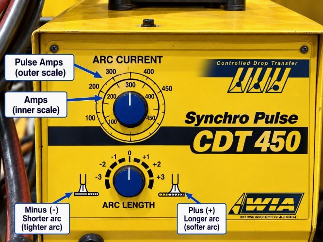
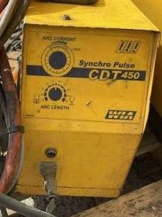
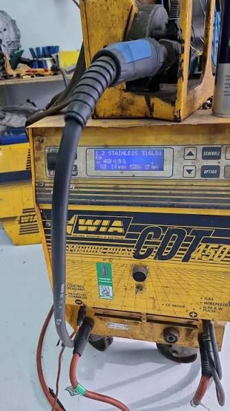
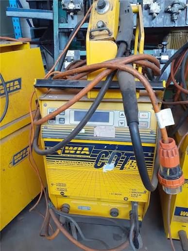
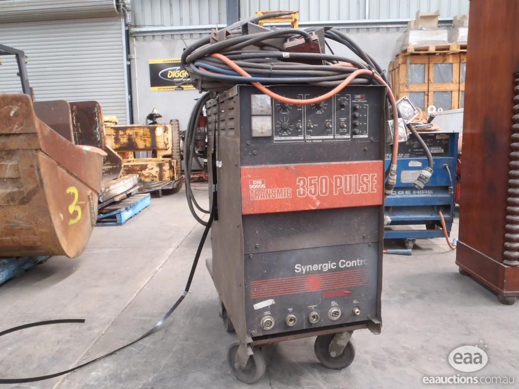
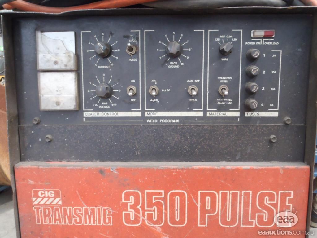
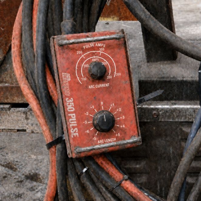
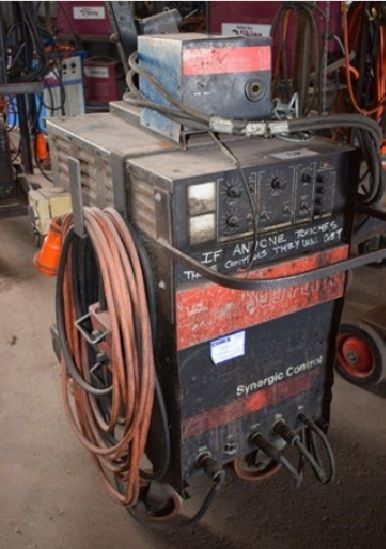
Photographs from the author’s collection and from Australian auction listings. Two have been digitally restored so the panel markings are legible.
Same facts, same numbers, same story. The advanced version adds the equations, the clause references and the point where the story stops being true.
Where the word comes from
It’s Greek. syn means together, ergon means work. Synergia, working together.
Note what it does not mean. It isn’t “one plus one equals three”. That meaning is modern, about 1957, and the management consultants flogged it to death. The welding meaning is the old one: two things working together instead of fighting each other.
Who came up with it
Someone called Amin, writing in Metal Construction in Britain, 1981. It’s a research term, not marketing, and it’s about 45 years old.
The problem was pulsed MIG. Too many knobs for anyone to set by hand: peak current, background current, frequency, pulse width, ramp rates. So Amin made the whole lot follow one input.
Britain named it. Australia already had it running. CSIRO had a pulsed current generator working in 1979, and Welding Industries of Australia sold it here from September 1983 as the Synchro-Pulse CDT. Two knobs on the front: ARC CURRENT and ARC LENGTH. That is this whole page, in a die-cast box, forty odd years ago. The photographs above are that machine.
What it’s actually doing, and this surprises people
It isn’t controlling your arc.
All a synergic line is, is a relationship between amps and volts, worked out for three things:
- what wire
- what size
- what gas
Somebody did a heap of work to find out what the volts should be for the amps, for every combination of those three. Then they wrote it down and loaded the list into your machine.
On a normal MIG you’ve got two knobs that have to agree. Wire speed sets your amps, through the burn-off. Volts sets your arc length. Only a narrow band of pairs actually works. Get it wrong one way and the wire stubs into the plate. Wrong the other way and you’ve got a long harsh arc, spatter and undercut.
Synergic just stores the pairs that work. You set one, it looks up the other.
Now the important bit. On a plain synergic machine, the thing holding your arc steady is not the computer. It’s the same physics that held it before synergic existed: when the current goes up the wire burns off faster, so the arc pulls itself back to length. That happened on a 1960s machine and it happens on yours. The synergic bit only saves you guessing the volts.
It’s a lookup table. Not a brain. Interpolation is joining the dots with a ruler: the maker measured four settings, say 100, 150, 200 and 250 amps, the machine draws a straight line between them, and every setting you pick in between comes off that line, not off anything anybody actually welded at.
Think of it as the modern version of the settings notebook that lives in a good welder’s toolbox. Somebody else’s notebook, written on somebody else’s job.
Three things to take away
- Wrong selection is confidently wrong. Tell it co2 when you’re on an argon mix and it’ll hand you spot-on settings for a gas you haven’t got. No fault, no warning, and a bead on the plate.
- Synergic isn’t the same as pulse. Synergic is how the machine gets set up. Pulse is how the metal crosses the arc. Plenty of welders think one means the other, and so do plenty of the people selling it.
- It only knows three things about your job. Wire, size, gas. It does not know your stick-out and it does not know your transfer mode. Those two are where the money goes, and they’re the rest of this page.
The quarter turn
Think about a two-stroke. Chainsaw, outboard, whipper snipper, whatever you’ve got out the back.
The factory set the carburettor needles for one fuel, at one altitude, at one air temperature. At sea level on 91 it runs sweet. Take it up the hill, or change the fuel, and you give the needle a quarter turn to suit.
Nothing stops you running the factory setting anywhere you like. It just runs rich or lean. And the only thing telling you is how it sounds.
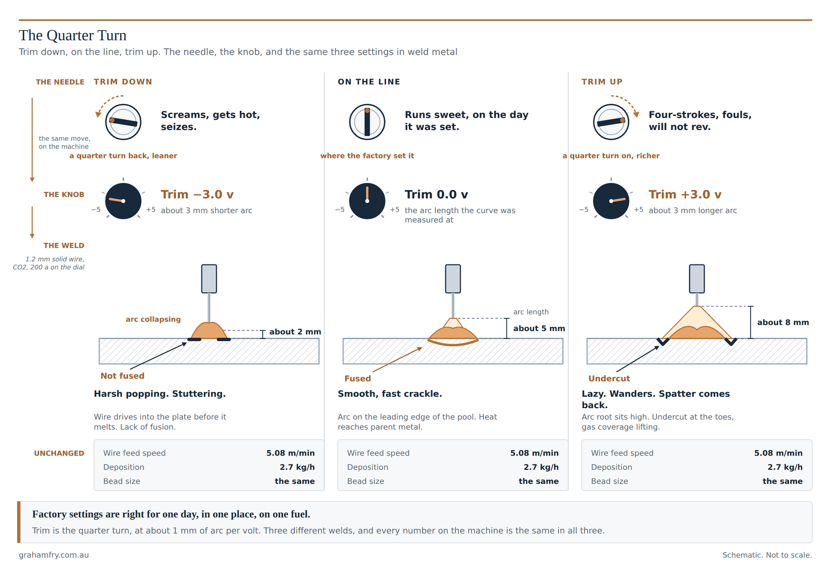
That’s a synergic machine. The stored curve is the factory setting. Trim is the quarter turn. And the arc is the sound.
Somebody in a laboratory ran that exact wire, in that exact gas, at that exact diameter, at one stick-out, and wrote down the right settings. Then they loaded the list into your machine. That list is the synergic line. Four points on a graph, usually. Straight lines in between. That’s it. It’s not clever and it isn’t watching you.
Lean and rich, in weld metal
Wind a two-stroke lean and it screams, gets hot and seizes. Wind trim down too far and the wire stubs into the plate before it melts. Harsh popping, stuttering, whiskers, and lack of fusion.
Wind it rich and it four-strokes, fouls and won’t rev. Wind trim up too far and the arc goes long and lazy, the arc root lifts off the leading edge of the pool, and you get undercut at the toes and porosity as the gas coverage lifts.
Same knob. Same two extremes. Same feedback, which is your ears. A dip transfer arc that’s right is a smooth fast crackle, like bacon. Spray is a smooth hiss. If it’s popping harshly, you’re lean.
Factory settings are right for one day, in one place, on one fuel.
So what does the primary knob do
It moves you along the list. Nothing else. On some machines that knob reads in metres per minute, on others it reads in amps, and on others it reads in millimetres of plate thickness. Same knob, three different units, and no manual tells you they’re the same knob. It’s like calling a length 25 mm, 2.5 cm or 0.025 m. One thing, three ways of saying it.
And this is the bit that costs money. When the dial says amps, you are not setting amps. You’re picking a point on the list, and the machine looks up the wire speed and the volts that go with it. The actual amps still depend on how far you’re holding the gun out, how good your earth is, and whether the tip’s shot. The machine has no idea about any of those.
So pick one unit and stay on it across the shop. Amps is the one worth standardising on, because amps is the number that turns up on every procedure sheet and every report you will ever have to defend, and it’s the one arc energy comes off. A shop where one welder dials amps, the next dials plate thickness and the third dials metres per minute has three mental models of the same machine, and not one of them lines up with the sheet. The makers were trying to simplify it. Mostly they’ve convinced people it’s three different things.
And trim
Trim is the quarter turn. Zero trim means you’re on the list, using the arc length the laboratory wrote down. Wind it up and the arc gets longer. Wind it down and it gets shorter.
Roughly a millimetre of arc per volt of trim. So plus 3 volts is about 3 mm more arc. Plus 5 is about 5 mm, and 5 mm is a lot of arc.
What trim is not is a heat knob. It doesn’t touch the wire speed, so your deposition doesn’t change and your amps barely move. Cigweld calls it Heat Control on the Transmig 355i and that name has done real damage, because someone chasing a fusion problem winds up the trim, gets a wider, flatter, prettier looking bead, and has not fixed the fusion.
It isn’t arc dynamics or inductance either, and those two get mixed up with it constantly. Different knob, different job. Trim moves the voltage, and voltage is arc length. That’s the lot.
People call volts heat for a reason, mind you. Lengthen the arc and you get more visible light, a more fluid pool and a wider bead, so it looks hotter. And the arc energy sum backs it up, amps times volts over travel speed. But most of the energy comes from the amps, and it has to: feed more wire and you need more energy to burn it off. Amps is wire feed by another name.
One knob, a different name on every machine, and none of the numbers transfer
Trim on a Lincoln. Arc length correction on a Fronius. Fine tuning on a Kemppi. Arc length on a Miller and a Migatronic. Heat Control on a Cigweld. Arc length correction in volts on an EWM. And on a Lincoln in stt mode, the same knob genuinely does change heat input, because in stt it adjusts the tail-out and the background current instead. One word, one knob, three different jobs depending on which mode is loaded. So when a welder is confused about trim, that isn’t them being thick as two short planks. That’s us not being consistent and not teaching it. They carry across what the last machine taught them.
The one that costs money: your stick-out
The list was written at one stick-out. On the 1.2 mm solid wire in co2 example in the tool above, Lincoln published it at 13 to 19 mm, so call it 16.
Now reach into a joint. Everybody does it. Your stick-out goes out to 25 mm.
The wire speed hasn’t changed. The volts on the display haven’t changed. The program hasn’t changed. Nothing on that machine has moved. And the amps at the arc have gone from about 200 down to about 174.
You’ve lost 13% of your current, and every number in front of you says you haven’t. Your deposition is identical, because deposition is just wire speed times cross section. So the bead looks the same size. It just isn’t fusing the same.
That’s cold lap on a machine that “was set right”. That’s the whole mechanism, and I see it constantly.
What to do about it
- Learn your nominal stick-out and hold it. Roughly 10 to 12 mm on 0.8 and 0.9 mm dip transfer, 15 to 20 mm on 1.2 mm spray, out to 25 mm on 1.6 mm cored. It’s in the tool above for whatever you’ve selected.
- Check the program matches what’s on the machine. Not the wire you meant to load. The one that’s actually in it, and the gas that’s actually in the bottle. A synergic machine will happily weld on the wrong program. It won’t fault, it won’t warn you, and it’ll still put a bead down.
- Never run cored wire on a solid wire program. Metal cored burns off faster at the same current because the current runs in the sheath, not the core. 1.2 mm metal cored puts down 5.4 to 6.4 kg an hour against 3.6 to 4.5 for solid the same size. Run it on the solid program and you get undercut. Thats documented, not a maybe.
- If you’re winding trim to the stops, stop and look at why. Next section.
You can run any line with any wire and any gas
Nobody tells you this part.
Nothing stops you running the wrong program. The machine will not fault. It won’t warn you. It’ll weld, and it’ll put a bead down that looks like a bead.
No 0.9 mm line in your machine? Load the 1.0 mm line, run the 0.9 wire on it, and trim the volts to suit. That’s a legitimate workaround and I wouldn’t blink at a welder doing it.
What it costs you is ‘accuracy’. The curve has stopped doing the work and you’re doing it by hand.
And the bill is smaller than you’d think one size away. Running 0.8 wire on the 0.9 program wants about half a volt of trim at 100 amps, and about 2.6 volts by 250. Go two sizes, 0.9 wire on the 1.2 program, and you need nearly 3 volts at 250 and 8 volts at 380, which is off the end of the knob.
So the rule’s simple. One size away is nearly free at the bottom of the range and gets worse as you wind it up. Two sizes away runs out of knob at the top. The gap always widens with current, which is why the borrow that ran beautifully on 3 mm plate falls apart when the same welder goes up to heavy section.
Gas is the same story, and the direction surprises people. Load a spray tuned argon program, run co2 on it, and you’ll be winding trim down, several volts, and you still won’t get spray, because co2 can’t produce it at any current. Lincoln’s own SuperArc L-56 sheet has 1.2 mm in straight co2 at 19 to 21 volts and 145 to 200 amps, short circuit, and the same wire in 90 argon 10 co2 at 27 to 30 volts and 285 to 340 amps, spray. Same wire, same page, and co2 sits right down the bottom. Going the other way you wind up. Know which way you’re borrowing and by how much.
Then write the trim value on the sheet. That’s the whole discipline. A borrowed program with the trim written down is a controlled process. A borrowed program with the trim left to whoever picks up the gun is not.
Trim at the stops is telling you something
If a welder consistently needs a lot more volts than the list says, the list isn’t wrong. One of three things is, and all three are ten minute checks:
- The stick-out is long. The extra resistance has dropped the current, so the list’s volts are now too low for the arc that’s actually there.
- The program doesn’t match the wire or the gas actually loaded. Change the gas and a trim of zero is a completely different voltage.
- Volts are getting lost between the machine and the arc. Four volts down long leads and dodgy connections on a 31 volt arc is documented. The machine sends what it was asked for. The arc never gets it. So the trim goes up to make up the difference.
Gun angle is the fourth, and it’s the one that beats the feedback loop entirely.
So log the trim next to the current on every machine in the shop. A fleet sitting near nominal has the right programs, has been set up properly, and has welders holding their stick-out. Anything on the stops, or past about plus or minus 3 volts, is telling you which of those three you’ve got. Costs nothing but a bit of time, and it’s the closest thing to a free diagnostic the equipment offers.
What it sounds like
- Trim too low, arc too short. Harsh popping. Stubbing. The wire drives into the plate before it melts and you can feel the feed motor labouring. Whiskers. Burnback to the tip if you keep going.
- Trim too high, arc too long. Lazy, wandering, wide. Spatter comes back. Undercut at the toes. And porosity, because the arc root is sitting up high and the gas column isn’t wrapping it any more.
- Right. Dip transfer is a smooth fast crackle, like bacon. Spray is a smooth hiss. If it’s popping harshly it’s either the trim or the wire speed, and the fix is not always trim.
And the gas, which the machine cannot see at all
No synergic machine senses gas. Not what’s in the bottle, not the flow, not a leak. And composition is the big one, because there’s no such thing as one argon co2 mix. Some shops run 80 argon 20 co2, some run 82/18, and then there are the tri mixes, argon with 16 per cent co2 and 3 per cent oxygen. Under ISO 14175 the first two are both M21, which covers anything from 15 to 25 per cent co2. The tri mix is M26, and your machine may not carry a program for it at all.
Then look inside the designation. Any component above 5 per cent can be delivered within plus or minus 10 per cent of its nominal value. Not ten percentage points, ten per cent of the number. So a nominal 20 arrives anywhere between 18 and 22, a nominal 18 arrives between 16.2 and 19.8, and both are fully compliant. That’s nearly six percentage points of co2 across two gases the machine holds one program for, and it has no way of knowing which bottle it’s being fed from. Enough to change how the arc sounds. Enough to want a volt of trim.
Straight co2 earns its own warning. Argon is a single atom and ionises into a smooth stable column. co2 has to be torn apart in the arc before it will conduct at all, and it can’t produce spray at any current. Wind the volts up on co2 expecting a nicer arc and you don’t get one. You get globular: big droplets, severe spatter, runs like a pig. A co2 procedure runs low volts on purpose. And running straight co2 in a modern shop is false economy, particularly with skills where they are, because you’re handing the welder a harder process and an erratic arc, and losing it again in spatter, to save a few dollars on gas.
Flow is the other one the machine can’t see. Turning the gas up to fix porosity can cause porosity: past roughly 21 L/min through a 16 mm nozzle the exit velocity creates a vacuum at the nozzle lip and pulls atmosphere into the plume. The working range is about 12 to 14 L/min on that nozzle. Not 28.
And the wire, which it can’t see either
Two spools can both say ER70S-6 and still run differently, because the standard allows a range, not a number. AWS A5.18 lets manganese sit anywhere from 1.40 to 1.85 per cent and silicon from 0.80 to 1.15. Those two are the deoxidisers, and they set how the pool wets, how the arc forms and how much silicate island you’re left picking off the top. A wire at the bottom of both bands and a wire at the top are both compliant ER70S-6, and they don’t run the same. Add the diameter tolerance, and copper coating on some and none on others, and it’s enough to sit you off the line.
Two reasons that matters more than it sounds. Silicon raises resistivity, and resistivity is what heats the stick-out, so two compliant wires don’t burn off at the same rate at the same current. And the wire isn’t only the thing being melted: iron vapour ionises at 7.9 electron volts against argon’s 15.76, so metal coming off the wire is a large part of what carries the current in the arc column. Change the chemistry and you’ve changed the conducting medium, not just the filler.
None of that is on the panel and none of it is in the program. It comes out as a wire that wants a different trim to the last one, on the same job.
Where the word comes from
Straight from the Greek. syn, together, plus ergon, work. Synergia meant joint work, cooperation.
It arrived in English in the 1650s as a theological term for human will cooperating with divine grace, and Jacob Henle picked it up in 1847 to describe the concourse of action between different organs. The meaning everybody now assumes, greater than the sum of the parts, is late. It dates to about 1957, it was popularised through Buckminster Fuller, and it was borrowed from pharmacology and metallurgy where two substances together did more than either alone. Then the management consultants got hold of it.
That history matters, because synergic control is not that kind of synergy. One plus one does not equal three inside a welding machine. It’s the older and truer meaning: two things working together instead of working against each other. No extra output. Just cooperation instead of argument.
Where it comes from in welding
Not marketing. It’s a research term, it’s British, and it’s traceable to one researcher.
M. Amin, Synergic pulsed MIG welding, Metal Construction 13(6) 349 to 353, 1981. Three more papers followed over the next six years: the pulse current parameters paper in 1983, microcomputer control of synergic pulsed MIG in 1986, and with Ahmed, Synergic control in MIG welding, in 1987. Metal Construction grew out of Metal Construction and British Welding Journal.
So the term is about 45 years old, and it was coined for a specific problem. Pulsed MIG had too many independent variables for a human to set at the machine: peak current, background current, pulse frequency, pulse width, ramp rates. Amin’s answer was to make all of them follow one input.
The usual line is that the Poms invented it and we improved it. Not this time. Britain named it, and Australia already had it running. Graeme Ogilvie started exploratory experiments at the CSIRO Division of Tribophysics in 1978 and had a thyristor pulsed current generator working in 1979, two years before Amin’s paper reached print. Welding Industries of Australia took it to market in September 1983 as the Synchro-Pulse CDT, Controlled Drop Transfer, with arc voltage and current sensing fed back to hold the drop transfer steady. Ogilvie took one of the three inaugural CSIRO Medals for Research Achievement in 1985. The machine welded Australia II and the flagpole on Parliament House, and it sold into shipbuilding overseas on aluminium and stainless, where the welds had to be right. Dates and the launch from CSIROpedia, Synchro-Pulse Controlled Drop Transfer Welding System.
And this is where the confusion starts, because the CDT was both. A pulsed transfer process and a synergic control, in the same box, in 1983. Load a program, turn one knob, and the machine scheduled the waveform off it. Two words for two different things, welded together in one product, and the trade has used them interchangeably ever since. It was a fabulous piece of gear, and the front panel of a CDT 450 is this whole page in a die-cast box: two knobs, ARC CURRENT and ARC LENGTH. One to move along the line, one to bias it. The photographs above are that panel, and the CIG Transmig 350 Pulse next to it does the same job with three switches for the three inputs and a knob marked FINE VOLTAGE for the trim.
They weren’t widely understood from the start either. As an apprentice I asked the tradesman whether the new synergic machine was any good, because I was keen to have a shot, and he told me the sparks don’t even burn. I found out that wasn’t the truth pretty quickly. The CDT was known for running an arc longer than most applications wanted, and you would often run out of adjustment. Which is exactly what the second knob was for, and exactly the knob nobody was taught to use. All I had to do was lengthen the earth lead and the long arc would have fixed itself.
It is not controlling the arc
This trips up nearly everybody, including a fair few of the people who sell these machines.
A synergic line is not arc control. It’s a relationship between amps and volts, built from three inputs: wire type, wire size, gas type. That’s the lot. Somebody did a heap of work to establish what the volts should be for the amps across every combination of those three, and the machine holds the answer.
Compare the two. Non-synergic gmaw gives you two knobs that must agree. Wire feed speed sets the current, through the burn-off relationship. Voltage sets the arc length. Only a narrow band of pairings works, and outside it you get stubbing one way or a long harsh arc, spatter and undercut the other. Synergic control stores the pairings that work. You set one variable and the machine reads off the matching one, and in pulsed mode every pulse parameter with it.
Now the bit that matters. On a plain synergic cv machine, nothing in there is controlling your arc. The arc is held by ordinary constant voltage self regulation, the same physics that held it before synergic control was invented: when the current rises the wire burns off faster, so the arc length restores itself. That happened on a 1960s machine and it happens on yours. The synergic layer never touches it. All it does is save the operator from guessing the voltage.
Where real arc control does exist, it’s a separate layer bolted on top and it is not the curve. In synergic pulse a waveform controller estimates arc length from the voltage and current on the pulse ramps and corrects it inside individual pulse periods. In an adaptive machine there’s a stick-out compensation loop with a declared envelope, and Lincoln’s R450 states its own as 12.7 to 31.8 mm. Both are closed loop control. Neither of them is the synergic line.
So the curve is a lookup table with interpolation. Not intelligence, and not control.
Three consequences
- Wrong selection is confidently wrong. Tell it co2 when you’re running an argon mix and it delivers precise settings for a gas you have not got. No fault, no warning, and a bead on the plate.
- Synergic is not the same thing as pulsed. Synergic is the control philosophy. Pulsed is a transfer mode. Plenty of welders think one implies the other, and so do plenty of the people selling it.
- The machine can’t tell what’s loaded. Not the wire, not the diameter, not the gas. Nothing in there senses any of it. All it holds is a relationship between amps and volts, and what you selected is only a pre loaded relationship. So don’t stand there thinking you haven’t got a line for your combination. Load one that’s close, trim it to suit, and write the trim down.
That last one has a tail, and the rest of this page comes out of it. You select three things. The curve assumes two more and never asks you about either: the mode of metal transfer, and the stick-out it was measured at. Neither is on the panel.
Factory settings are right for one day, in one place, on one fuel.
What the curve actually is
Given all that, the definition worth quoting is Norrish’s, because it’s the only one in print that names the thing being held:
Norrish 2017
“Synergic control is any system (open or closed loop) by which a significant pulse current parameter (or the corresponding wire feed speed) is amended such that an equilibrium condition is maintained over a range of wire feed speeds (or average current levels).”
Norrish, J. (2017), Welding in the World 61(4) 755 to 767, doi:10.1007/s40194-017-0463-8. University of Wollongong, which makes it the right citation for an Australian readership.
Three things in that sentence that nobody else says. It admits open or closed loop. It’s framed on ‘equilibrium’, not on operator convenience. And it started as a pulsed transfer definition and got generalised later, which is why twi’s own faq still describes synergic as a variant of pulsed mig and is now wrong.
Note also what the term is not. There is no definition of “synergic” in any edition of IEC 60974-1. IEC 60974-14:2018 uses the word without defining it: Annex C is titled “Slope, pulse and synergic controls” and C.4 is “Pulsed MIG and synergic controls”. The term with an iso definition behind it is ‘waveform controlled welding’, from ISO/TR 18491. AS/NZS 1554.1:2014 clause 1.1 Note 2 uses both, and that note is the only place in the whole standard where synergic control is named.
Three things get called synergic, and only two of them are
- Synergic pulsed gmaw. The original meaning. A stored parameter set, peak current, peak time, background current, background time or frequency and the ramp rates, scheduled off wire feed speed to hold one drop per pulse across the range. The parameter list is confirmed at patent level: Lincoln US20110204034A1 names pulse frequency, peak current, background current, current ramp rates, pulse width and pulse curvature, with interpolation between table entries.
- Synergic cv. Wire feed speed is the single knob and the target voltage is looked up from a stored curve. The Power Wave R450 manual says it plainly: “for each wire feed speed, a corresponding voltage is preprogrammed into the machine through special software at the factory”. The regulation underneath is still ordinary cv self regulation. Synergic only removes the operator’s need to guess the voltage.
- Controlled short circuit and waveform processes: stt, rmd, cmt, ColdArc, lsc. These are not synergic lines. They’re event driven closed loop current controllers, triggered on short circuit detection and on the dv/dt necking signature, resolving events of the order of 0.75 ms. They’re wrapped in a synergic interface, which is exactly why everybody conflates them. cmt is mechanically closed loop, reversing the wire. The mechanism that produces the low spatter is not the curve.
Confusing the third with the first two is the most common error in trade literature, and it’s the reason people credit “synergic” with things it has nothing to do with.
The method: what a synergic line is, and what trim does to it
The curve itself
A synergic line is a one dimensional look-up table or piecewise function, indexed on wire feed speed, returning a matched parameter vector valid for one combination of wire chemistry and class, wire diameter, shielding gas composition and intended mode of transfer. For synergic cv the returned vector is one number, the target arc voltage. For pulsed synergic it’s the whole waveform descriptor.
The internal structure is documented, and it’s smaller than people imagine. A Migatronic COMMANDER BDH holds three curves per synergic program, one for wire speed against current level, one for welding voltage, one for arc adjust. Pulsed mig adds three more for the pulse parameters. Each curve is defined by four calibration points creating three intervals, with linear interpolation between them. Try to define a breakpoint without a higher current level than the one before it and the machine throws Err A- and refuses. That monotonicity constraint is what makes single valued inversion possible.
Four points. That’s a synergic curve. The tool above plots the published breakpoints as dots precisely so that’s visible, because it’s the least appreciated fact in the whole subject.
Why the curve is single valued, and why that forces trim to exist
The curve is a function of one variable. It returns the voltage that produces the intended arc length and current only at the stick-out it was fitted at. It cannot know the actual ctwd, the joint geometry, the position, the plate temperature, the gas flow, or whether the operator wants a tighter or a softer arc. Trim is the operator’s single degree of freedom against a fixed table. It is a bias on the table’s output, never a replacement for it.
In pulse, voltage cannot be a set point at all, and Lincoln says so in the Power Wave 455M manual: “when pulse welding, the arc voltage is highly dependent upon the waveform. The peak current, background current, rise time, fall time and pulse frequency all affect the voltage.” A preset voltage is therefore impractical, and the maker hands you trim instead. That’s the whole answer to “why is there no volts knob in pulse”, and almost nobody teaches it.
What trim physically acts on, which is not the same in the two modes
- Synergic cv: a voltage offset applied to the stored voltage curve. Documented in volts by three independent makers. Migatronic: the trim value “determines the number of volts by which the voltage synergic curve should be adjusted (up or down)”, minus 9.9 to plus 9.9 v. EWM: “the arc length (welding voltage) can be adjusted for the welding task in hand by plus or minus 9.9 v”. Kemppi: FineTuning “adjusts the arc voltage of the curve within certain limits”.
- Synergic pulse: an arc length target that the controller services by modulating the waveform, most commonly the background current. Kemppi documents this explicitly, FineTuning minus 9.0 to plus 9.0 for “adjusting base current and arc length”, and WiseRoot BaseCurrent minus 50 to plus 50 “for adjusting arc length within specified limits”. The physics is sound: background current doesn’t detach droplets, so changing it changes the burn-off between pulses and therefore the mean arc length, without disturbing the one drop per pulse detachment condition that the peak sets. Explicit for one maker, inferred across the industry.
- Same knob, three jobs on one machine. The Power Feed 15M manual: trim does not apply in cv modes at all, voltage control is used instead; in pulse synergic it adjusts arc length; and in stt “trim changes the heat input by adjusting the tailout and background portion of the waveform”.
The conventions, and why they don’t transfer
| Maker and family | What it is called | Range | Units | Nominal |
|---|---|---|---|---|
| Migatronic, EWM Phoenix | Arc length, arc length correction | minus 9.9 to plus 9.9 | volts | 0 |
| EWM Picomig | Arc length correction (welding voltage) | minus 5 to plus 5 | volts | 0 |
| Kemppi FastMig, X5, Master M | Fine tuning | minus 9.0 to plus 9.0, 0.5 v steps; X5 in 0.1 v steps | volts | 0.0 |
| ESAB Aristo U8, U82 | Voltage as an offset from the synergic line | 0.25 v steps | volts | 0 |
| Cigweld Transmig 355i | Heat Control | up to plus 5 from preset, 0.1 v steps | volts | preset |
| Fronius TPS/i | Arc length correction | minus 10 to plus 10 | per cent of the curve value | 0 |
| Fronius TPS 320i | Arc length correction | minus 10 to plus 10 | no units stated at all | 0 |
| Lincoln Power Wave, Power MIG | Trim | 0.50 to 1.50 | dimensionless multiplier | 1.00 |
| Millermatic and Multimatic 255 | Arc Length | 0 to 99 | dimensionless index | 50 |
| Cigweld BlueVenom XF353 | Volts Trim (TRIM/V) | minus 5.0 to plus 5.0 | volts | 0, display reads Syn |
| ESAB QSet | Step count | minus 18 to plus 18 | steps | 0 |
There’s an Australian angle in that table. One Australian industrial supplier’s mig catalogue, counted by models stocked, runs Kemppi 10, ESAB 8, EWM Group 5, WIA 4, Lincoln 3, Cigweld 2. The european brands express the control in volts. The american brands express it as a dimensionless multiplier or index. A welder moving between an EWM Picomig and a Lincoln Power Wave in the same shop is turning knobs measured in two units that do not convert. And Cigweld, which has the deepest trade recognition in this country, is ESAB owned and calls it Heat Control, while WIA is Lincoln owned. Same underlying logic, Australian badges, three mental models.
Do not invent a volts equivalence for the Lincoln scale. Lincoln doesn’t publish one, and the manual explains why: “the exact voltage for a given wire feed speed can only be predicted when all the pulsing waveform parameters are known”. Cameron makes the same point independently and adds the one that matters most, that a trim setting of 1.00 produces a different actual voltage the moment you change the electrode, the shielding gas or the wire feed speed. The correct method is empirical. Set the wire feed speed, sweep trim, record the displayed volts at each step, and build a local calibration for that mode, wire, gas and stick-out. And Lincoln, which invented the dimensionless scale, now ships the Power Feed 42 with “Display Trim as Volts” set to yes by default.
Which raises the practical problem. Write plus 2 v on a wps and that instruction only means something on a machine that expresses trim in volts, in the same mode it was measured in, with the same total lead loop length: interconnecting leads, work return and torch. Hand the same sheet to a shop running a different machine and you haven’t made it simpler, you’ve made it ambiguous. The value that matters is arc voltage, measured with a decent tong tester between the wire feeder and the job, not the digital readout. Record the trim by all means, and teach the welders what the number is and is not worth.
This is a large part of why a procedure qualified on one machine does not travel to the next one and give the same result. It is not the welder’s fault. Managing that difference, and training for it, is the welding supervisor’s job.
The physics under the curve
The curve is empirical, but the shape it encodes is not arbitrary. Melting rate is Lesnewich’s burn-off relation:
Two consequences fall straight out of that, and both of them are why this page exists.
First, current is determined, not chosen. Set the wire feed speed and set the extension, and there’s exactly one current at which melting rate equals feed rate. That’s the equilibrium in Norrish’s definition. Inverting the equation gives the current directly, and it’s the arithmetic the tool above runs:
And that’s the whole basis of the synergic idea. If current is a determined function of wire feed speed, then so is the correct voltage, and it can be stored.
Second, sensitivity to stick-out is calculable. Differentiate at constant wire feed speed:
With Richardson’s 1.2 mm coefficients at 15 mm extension that predicts 6.6 a per mm at 300 a. Measured independently: Miller, gmaw spray, 15.9 to 25.4 mm ctwd took 282 a down to 213 a, which is 7.3 a per mm. ewi, gmaw-p at 5.1 m/min wire feed speed, 19.1 to 28.6 mm took 300 a down to 225 a, which is 7.9 a per mm. Within about 10%, from published coefficients, with no fitting. That’s a model you can trust with a decision.
Note that the sensitivity is not constant. It scales roughly with current, so a 5 mm stick-out error costs about 20 a at 200 a and about 40 a at 350 a. The rule of thumb for solid wire in the spray range is about 7 a per mm, or about 2.5% of set current per mm. Below that it’s less. The tool computes it for whatever operating point you’ve set rather than quoting the headline figure at you.
Cored wires are a different physical object, not a variant. Current flows almost entirely in the metal sheath, so the effective conducting area for the joule term is an annulus, not a circle. Since b carries the inverse square of area, b is much larger than the nominal diameter suggests, and the wire burns off faster at the same current. That’s the actual reason 1.2 mm metal cored deposits 5.4 to 6.4 kg/h against 3.6 to 4.5 kg/h for solid wire the same size. It’s also why cored wire synergic curves have to be separate program entries, and why running metal cored on a solid wire program causes undercut. And it’s why Hobart’s FabCOR sheet grades nominal ctwd by diameter, 13 mm at 0.9, 19 mm at 1.2, 25 mm at 1.4 and 1.6. The curve and the nominal stick-out are a matched pair.
Worked example: 1.2 mm solid wire in co2, and one reach into a joint
Set the tool above to carbon steel solid wire, 1.2 mm, co2 (C1), synergic cv. Lincoln’s published SuperArc L-56 rows for that combination give three real breakpoints, and the third one is the operating point most Australian structural shops actually live at.
| Step | Wire feed speed | Volts | Amps | Stick-out | Arc energy at 300 mm/min |
|---|---|---|---|---|---|
| On the curve, as published | 5.08 m/min | 21.0 | 200 | 16 mm | 0.84 kj/mm |
| Reach into the joint, nothing else touched | 5.08 m/min | 21.0 | 174 | 25 mm | 0.73 kj/mm |
| Change | nil | nil | minus 13% | plus 9 mm | minus 13% |
The arithmetic, so you can check it. Nominal electrode extension at 16 mm ctwd and a 4 mm arc is 12 mm. Solving the burn-off equation at 12 mm gives 204 a against the 200 a Lincoln published, which is 2% out and a fair validation of the coefficients. Go out to 25 mm ctwd and the extension is 21 mm, and the same equation gives 174 a. The local sensitivity is 4.3 a per mm at nominal, falling to 3.1 a per mm as the extension lengthens, so the integrated loss over 9 mm is about 30 a.
Now the compliance consequence, and it’s the reason this is not an academic point. AS/NZS 1554.1 Table 4.11(A) makes a change of more than plus or minus 10% of the specified mean welding current an essential variable, and a change of more than plus or minus 20% in electrical stick-out likewise. Item letters and figures verified against the 2000 edition; buy the current standard before citing item letters against a 2014 date.
So a welder reaching into a joint on a machine nobody has touched has just put the weld outside two essential variables at once. Current 13% down, past the 10% band. Stick-out 25 mm against a nominal 16, which is 56% out, past the 20% band. Zero machine changes. Nothing on the display moved. And deposition is identical, so the bead is the same size and looks right.
The competence problem in one paragraph: the range on the sheet doesn’t weld anything, the welder does, and the only variable on that sheet a welder can actually obey without a meter is stick-out.
Where the story ends
The quarter turn is honest about the factory setting, about trim being an override you make by hand, and about the arc being the feedback. Three places it stops.
It has nothing to say about the shape of the record. A carburettor needle is continuous. A synergic line is four points with straight lines assumed between them, and that discreteness matters: near the ends of a curve you are operating where it was fitted on the fewest data points and where adaptive authority is smallest. Qualify there, or move to a different curve.
It has nothing to say about waveform. In synergic pulse there is no single arc length being held. There is a droplet detached once per pulse by a peak current, with the mean arc length managed by the background current between pulses. A needle cannot carry that, and the tool above does not pretend: select synergic pulse and the voltage chart refuses to draw a centre line, because the centre line does not exist as a published number.
And it has nothing to say about adaptive control. A machine with a genuine adaptive layer, and Lincoln’s R450 declares its envelope as 12.7 to 31.8 mm of electrical stick-out variation, is doing something a carburettor cannot: sensing the arc length from the voltage and current on the pulse ramps and correcting it inside individual pulse periods, so arc length is held independently of extension. Fronius goes further with a penetration stabiliser that holds the current and lets the wire feed speed float, which inverts the whole architecture. A machine in that mode is no longer synergic in the classical sense. Most shops that own the feature have never turned it on.
What the curve cannot see
The machine reads its own output terminals. In all but a handful of adaptive machines, that is the entire extent of its awareness. Four things sit outside it, and all four move the arc away from the number on the wire feeder display. Stick-out is the worked example above. The work return circuit is the 4 v case below. The other two are the gas and the wire, and neither is sensed at all.
The gas: one designation, six percentage points of co2
There’s no such thing as one argon co2 mix. Some countries run 80 argon 20 co2, others 82/18, and then there are the tri mixes, argon with 16 per cent co2 and 3 per cent oxygen. Under ISO 14175 the first two are both M21, a designation that covers anything from 15 to 25 per cent co2. The tri mix is M26, and plenty of machines carry no program for it at all.
Then look inside the designation. Any component above 5 per cent may be delivered within plus or minus 10 per cent of its nominal value. Not ten percentage points, ten per cent of the number. A nominal 20 arrives anywhere between 18 and 22. A nominal 18 arrives between 16.2 and 19.8. Both are fully compliant, and the spread across the two is nearly six percentage points of co2 for one program and one trim setting. The machine has no way of knowing which bottle it is being fed from. It is enough to change how the arc sounds and enough to want a volt of trim, and it is invisible on every document in the shop except the gas certificate.
The direction of the correction is the useful part. Load a spray tuned argon program and run co2 on it and you’ll be winding trim down, several volts, and you still won’t get spray, because co2 is a molecular gas that has to be dissociated before it will conduct and it cannot produce axial spray at any current. Lincoln’s own SuperArc L-56 sheet puts 1.2 mm in 100 per cent co2 at 19 to 21 v and 145 to 200 a, short circuit, and the same wire in 90 argon 10 co2 at 27 to 30 v and 285 to 340 a, spray. Same wire, same page, and co2 sits right down the bottom.
Which leads to the commercial point, and I’ll own it as opinion. Running straight co2 in a modern shop is false economy. You are handing a welder an erratic arc and a harder process at a time when skills are already stretched, and giving back in spatter and metal recovery whatever you saved per cubic metre. The economics of shielding gas deserve their own article, and they will get one.
The wire: two compliant spools that don’t run the same
Two spools can both say ER70S-6 and run differently, because the classification is a range, not a number. AWS A5.18 permits manganese from 1.40 to 1.85 per cent and silicon from 0.80 to 1.15. Those are the deoxidisers, and they set how the pool wets, how the arc forms and how much silicate island is left on the cap. A wire at the bottom of both bands and a wire at the top are both compliant. Add the diameter tolerance in ISO 544, and copper coating on some and none on others, and the accumulation is enough to sit you off the line.
Two mechanisms make that more than a curiosity. Silicon is a powerful resistivity raiser in iron, and resistivity is what heats the electrode extension, so two compliant wires do not burn off at the same rate at the same current: the joule term in the melting rate equation is not the same wire to wire. And the wire is not only the thing being melted. Iron vapour ionises at 7.90 eV against argon’s 15.76 eV, so metal vapour coming off the electrode carries a large share of the current in the arc column, enough that it produces a central minimum in arc temperature. Change the chemistry and you have changed the conducting medium, not just the filler.
Cored wire is not a variant of this, it is a different object, and the physics is in the melting rate section above. Current runs in the sheath rather than the core, sheath thickness is the maker’s own choice, and two cored wires of the same class and diameter do not share a conducting area. Run any of it on a solid wire program and you will be a long way off the line, with undercut to show for it.
None of this is on the panel and none of it is in the program. It arrives as a wire that wants a different trim to the last one, on the same job, and it is the reason trim values do not transfer between shops even when the machines match.
Why the displayed numbers are not the numbers
Three errors stack here, and people usually know about none of them.
One, the averaging error on a waveform. Norrish’s measured spot checks, 5 khz sampling on an AMV 4000 logger:
| Mode | Mean current | Conventional calculation | True arc energy | Error |
|---|---|---|---|---|
| Spray transfer | 255 a | 0.79 kj/mm | 0.79 kj/mm | 0 |
| Conventional dip | 106 a | 0.41 kj/mm | 0.38 kj/mm | minus 8.3% |
| Waveform controlled dip | 54 a | 0.27 kj/mm | 0.25 kj/mm | minus 4.7% |
| Pulsed transfer | 140 a | 0.22 kj/mm | 0.29 kj/mm | plus 23% |
Read that table three times. First, the error is zero for conventional spray transfer. This is not a gmaw problem, it’s a waveform problem, and a shop running plain cv spray can keep using volts times amps over travel speed. Second, the sign reverses. For pulsed the conventional figure understates the true arc energy by about a quarter. For dip, conventional and controlled alike, it overstates it. If you’re holding an upper arc energy limit on a q&t or tmcp steel and you’re welding pulsed, your paperwork is optimistic and you may already be over the limit. Third, and this is the one to put in front of a client who thinks it’s academic, the downstream consequence is far bigger than the input error: on the conventional dip case Norrish reports the calculated t8/5 came out 46% longer than the naive figure suggests, because the cooling time relation is non-linear. An 8% error in became a 46% error out.
Two, the instrument tolerance. EN 50504:2008 clause 4 Table 1 permits a standard grade power source, one built to EN or IEC 60974-1 with no additional accuracy claim, plus or minus 10% of the true value on displayed current and voltage across the top three quarters of its range. Ten per cent on current and ten per cent on voltage compounds to roughly plus or minus 20% on the product, before you reach the waveform problem at all. IEC 60974-14:2018 Table 1 and Table 2 cell values not verified from a clean rendering; the EN 50504 figures are.
Three, the sensing point. The machine’s voltmeter reads at its own terminals, not at the arc, so it always reads high. A documented case: 4 v lost through leads and connections on a 31 volt arc, which is a 13% error, requiring 35 v at the supply. The machine sent what it was asked for. The arc never got it, so the trim goes up to make up the difference and now there are two faults stacked on each other. With short leads, about 4 m, the difference is negligible. Ammeter readings are unaffected by cable length, being series values. And note the consequence for machines with remote voltage sensing: the same program with the sense lead connected and disconnected is not the same weld. The field check costs nothing: clamp on the work, not the table, and put a hand on the connections after a run. Warm means resistance.
ISO/TR 18491:2026 clause 7.4 gives a procurement test you can use today. An acceptable meter is “often identified by the terms ‘true energy’, ‘true power’, or ‘power factor'”. One marked “kVA”, “DC power” or “average power” is not acceptable. Clause 7.2 and Table 2 also name the sensing point for process 13(x): the connection in the wire feeder. A wps quoting a voltage without a sensing point is quoting an unfalsifiable number.
What a wps has to carry, and what breaks when it doesn’t
ISO 15609-1:2019 clause 4.4.9 expressly permits recording “pulse welding details (machine settings, programme selection and all pertinent information of the process)”. So a shop writing “program 27, trim 0” hasn’t broken a rule. The consequence is in the last two sentences of clause 4.4.10:
ISO 15609-1:2019 clause 4.4.10
“If the equipment does not permit control of one of either variable, the machine settings shall be specified instead. The range of application for the WPS shall then be limited to equipment of that particular type.“
Recording only the program number collapses the wps’s range of application onto that machine type. The document stops being a welding procedure specification and becomes a machine specific recipe. Sell the machine, buy a different brand, or take a firmware update that renumbers the synergic lines, and the procedure is gone along with every hour of pqr testing behind it.
Stack that against ISO 15614-1:2017 + Amd 1:2019 clause 8.5.2.3.2, which at level 2 makes the power source manufacturer and the waveform control mode essential variables, and requires a new qualification test on a change of either. Two independent locks: brand locked by the qualification standard, machine type locked by the wps standard.
Norrish states the consequence plainly: where a procedure is qualified using a waveform controlled process, production welding needs “the same power source manufacturer, model, program and synergic lines”.
The transfer mode rules, which run in opposite directions
This catches people, so it’s worth setting out side by side.
- Procedure. ISO 15614-1 clause 8.5.2.3.1, as replaced by Amd 1:2019: “the qualification using short circuiting transfer qualifies only short-circuiting transfer. Qualification using spray, pulse or globular transfer qualifies spray, pulse and globular transfer.” So spray to pulsed is not a requalification. Same architecture as ASME IX QW-409.2, whose boundary per ASME’s own form QW-484A is “spray, globular, or pulse to short circuit-GMAW”, and AS 3992:2020 clause 5.1(c), which drafts “waveform-controlled arc” as a peer of spray and globular.
- Welder. ISO 9606-1:2012 clause 5.2: “qualifying the welder for dip (short-circuit) transfer mode (131, 135 and 138) shall qualify him for other transfer modes, but not vice versa.” The person qualified on dip covers everything. The person qualified on pulse does not cover dip.
So the direction of coverage flips depending on whether you’re talking about the procedure or the person, and the reason is obvious once it’s stated: dip is the harder mode to control and the one that produces lack of fusion, so it’s the harder test. A welder tested on synergic pulse is not qualified for conventional cv dip transfer.
One more trap. Clauses 8.5.2.3.2, .3 and .4 are all prefaced “For level 2”. At level 1 the waveform control mode is not an essential variable at all. A fabricator qualifying to level 1 to satisfy an asme-leaning client gets no waveform lock whatsoever.
The auditor’s list
Record the program so the welder can set the machine. Record the following so an engineer can rebuild the weld on somebody else’s machine.
- Wire feed speed range, in m/min. The only parameter a synergic machine actually commands and the only machine independent one. ISO 15609-1 clause 4.4.9 requires it only for mechanised and automatic welding, which is a genuine gap for hand held gmaw. Record it anyway. Weld Australia TGN-SG06 section 6.15 makes the technical case, that on a waveform machine you cannot reliably measure the amperage, and section 6.16 makes the supervisory one, that it’s a check on the current meter’s calibration.
- Contact tip to work distance. Everything above.
- Travel speed range, and therefore run length and time, not a dial reading.
- Arc energy range by method B or C of ISO/TR 18491 clause 6, from instantaneous energy or instantaneous power, never method A. State which method on the face of the wps: ISO 15614-1 clause 8.4.7 requires that “the kind of calculation, either heat input or arc energy, shall be documented”.
- Where the voltage was sensed.
- Mode of metal transfer, in words. Essential in QW-409.2, in ISO 15614-1 8.5.2.3.1 and in AS 3992:2020 5.1(c). It is not an essential variable in AS/NZS 1554.1 clause 4.11, which is a defect in that standard rather than a licence to omit it.
- Shielding gas to ISO 14175 including manufacturer and trade name, and consumable make and trade name, not just classification. The synergic line is calibrated to a specific gas and a specific wire. The program means nothing without both.
- Power source manufacturer, model and firmware version, the waveform control mode by its proper name, and every offset at its actual set value: trim, arc length correction, inductance, dynamic, pulse correction. Plus the pulse parameters where the machine exposes them.
- Evidence the machine’s own displays are calibrated or validated. On a waveform machine the displays are the only readings you can use, so their calibration is load bearing. IEC 60974-14:2018 is the standard for it. EN 50504:2008 clause 6 set the interval at yearly with a three month initial recheck.
The business case, honestly
The legitimate case for synergic control is variability reduction and faster changeover, not peak performance. It narrows the spread of parameters selected across a variable operator population. ESAB’s framing, “reduces setup and changeover time for everyone”, is defensible.
Two facts bound the claim, and both come from independent sources rather than manufacturers.
The first is twi’s survey of its industrial and professional members. Average repair rates in oil and gas and power run 1 to 3%, with peaks of 25% at specific locations and exceptional cases to 55%. The highest rates concentrate at root runs, fillet welds and areas of limited access. And the three dominant factors are welder skill level, weld location and accessibility, and poor fit-up prior to welding. Read that against the sales proposition. Synergic control addresses none of the three.
The second is that I went looking for independent quantification of synergic control’s own contribution to productivity or quality on manual gmaw, isolated from the pulse waveform or a consumable change, and there isn’t any that I could find. There’s good published work on pulsed against cv heat input and process efficiency, and on adaptive control in robotic welding. Nothing on the curve itself. Every figure in circulation is manufacturer or distributor sourced, and the headline one, three to four times the travel speed, is benchmarked against stick and tig, not against the cv gmaw machines the buyer already owns.
What the curve does control is worth having. Deposition efficiency inside gmaw runs 92 to 98% depending on gas and transfer mode, and that six point spread is decided entirely by which program somebody loaded. On 4.5 tonnes of deposited weld metal it’s roughly 300 kg of wire. Labour is typically 85% of total welding cost and arc-on time averages about 20%, which is 12 minutes of arc in the hour, so a wire with a published deposition rate of 9 kg/h delivers about 1.8 kg/h in the real world. Setup errors are labour hour errors, not consumable errors, and anyone arguing about the cost of a better gas mix against the cost of grinding time has the decimal point in the wrong place.
The documented failure pattern for a synergic fleet is worth knowing before you buy one. A fabricator with 250 welders and a mixed fleet of Power Wave 455 and 655, Idealarc 400 and S500 set out to move to pulse. Fleet heterogeneity defeated standardisation, because no two models use the same pulsing programs, so a shop with three machine generations cannot write one wps. The unbudgeted prerequisite was the electrical circuit: work clamps and power connections have to be right, because added resistance warms connections and degrades the feedback the pulse controller depends on. Vendor opacity blocked the paperwork, and a qa department that cannot document the controlled variables cannot qualify the procedure, so the shop reverts to cv where it can. And nobody had asked the first question, which their welding engineer eventually put to the buyer as: what do you do that makes you think you need pulsing when you’ve been using standard cv for so long?
What worked in that case wasn’t the equipment. Trials on a few machines, a tight identified window of 260 to 280 a and 25 to 27.5 v, the settings locked down, structured training on the actual kit, strict wps compliance, and the objective set as making the correct size weld rather than making it faster.
So be clear about what you have bought. The starting point is real and good equipment is worth having, but good equipment does not translate into faster, better welds on its own. Budget for the change, not just the hardware: commission the leads, clamps and work return, get the right wire and gas, and train the welders on what synergic does, what it does not, and what is likely to go wrong. Do none of that and the new gear creates more problems than it solves. That is change management and process optimisation, and it is the competence the industry is short of. Do not buy synergic machines and expect a solution. It is not written into the curves.
Synergic reduces variability in what the machine commands. It does nothing to variability in what the arc receives. That’s the technical heart of the whole subject, and it’s also the honest answer to a purchase order.
Fault to cause, cheapest check first
Two principles before the table, because they save more time than the table does.
Principle 1, revert to manual cv to isolate the fault
Every machine here has a manual mode. ESAB has a clean toggle, Synergy off or on, on the same voltage knob. Miller’s Multimatic 255 manual has the clearest single sentence any maker offers: the left knob “adjust[s] voltage in MIG mode, arc length in Pulsed MIG mode”. If the arc is stable in manual cv at equivalent volts and wire feed speed but unstable in synergic, the fault is the program or the sensing. If it’s unstable in both, the fault is mechanical or electrical. It’s the most useful test available to a supervisor and it costs nothing.
Principle 2, trim position is data
Log it next to the current, and the wire feed speed where the machine shows it, on every machine in the shop. A fleet sitting near nominal has correct programs and welders holding their stick-out. A fleet on the stops, or habitually past about plus or minus 3 volts, is telling you the programs don’t match the consumables, or the welders don’t hold ctwd, or the circuit is losing volts. Which of the three is a ten minute check.
| Symptom | Most likely | Then check | Then check |
|---|---|---|---|
| Wire stubbing into the plate, feed motor labouring | Trim or voltage too low for the wire feed speed | Wrong program: diameter set larger than the wire actually loaded | Drive roll tension, liner obstruction |
| Stuttering and popping at arc strike, “machine gunning” | Excessive standoff at the strike, loose grip on the gun | Voltage too low for the wire feed speed, raise 1 v at a time | Spool brake too tight, wire slowing before ignition |
| Harsh, narrow, digging arc | Trim or arc length too low | Arc control or inductance set too tight | Confirm the program before touching either |
| Arc long, lazy, wandering | Trim or arc length too high | Wrong gas or wrong program, an equal ranking documented cause | ctwd too long, then arc blow |
| Welder habitually at maximum trim | ctwd habitually too long | Program does not match the consumable or the gas | Volts lost in leads, connections, work return |
| Welder habitually at minimum trim | Program is for a larger diameter or a more co2 rich gas than in use | ctwd too short, nozzle spatter loading | Gun angle beyond the feedback compensation range |
| Amps read low at the correct wire feed speed | ctwd too long: 10 mm out to 25 mm took 200 a down to 150 to 160 a in a measured test | Worn or keyholed contact tip | Poor work return, connections warm to the touch |
| Amps read high at the correct wire feed speed | ctwd too short | Wrong wire diameter actually loaded | Meter error, plus or minus 10% of range is normal |
| Excess spatter in pulse | Wrong gas for the program | Wrong wire diameter selected | Worn tip, inconsistent wire delivery, low inductance |
| Excess spatter in dip | Trim or voltage too low for the wire feed speed | Inductance too low | co2 rich gas on an argon program |
| Burnback at the contact tip | Wire feed slowing before arc ignition | Liner, drive rolls, spool brake tension | Contact tip bore keyholed |
| Porosity, general | Gas flow too high: over about 21 L/min through a 16 mm nozzle aspirates air | Excessive wire extension, limit to about 13 mm past the nozzle | Nozzle spatter build-up, gas leak in gun or hose, draught |
| Porosity at weld starts only | Start of weld surge flow, measured over 100 L/min on a standard hose | Purge time and hose volume | Contamination at the start point |
| Undercut at the toes | Trim or arc length too high, arc too wide | Metal cored wire on solid wire parameters | Travel speed too fast, gun angle, arc blow |
| Cold lap and lack of fusion with settings that look right | ctwd long, current down 20 to 25% at unchanged wire feed speed | Arc riding the puddle instead of the leading edge, gun angle outside 0 to 15 degrees | Trim too low, base metal contamination |
| Lack of sidewall fusion in a narrow gap | Arc blow deflecting the arc off the sidewall | Work return position and symmetry | Arc length too long, a longer arc is easier to deflect |
| Burn-through | Program selected by nominal thickness with no allowance for fit-up | Trim or voltage too high, wire feed speed too high | Travel speed too slow, heat build-up late in the run |
| Heat input from the display fails the wps limit | Averaging error: about 23% on pulsed, 8% the other way on dip | Meter tolerance, plus or minus 10% of range | Sense point at the terminals not the arc: 4 v on a 31 v arc is 13% |
| Connections warm to the touch after a run | Added circuit resistance degrading the pulse feedback | Work clamp condition and contact area | Lead condition, connector torque |
| Machine “welds rough” and no parameter fault can be found | Wire feed instability partly masked by the arc regulator | Liner, drive rolls, spool brake, tip | Compare in manual cv to isolate the program from the circuit |
That last row deserves a note, because it’s a synergic specific trap that I’ve not seen written down anywhere. On a plain cv machine a welder feels a feed problem immediately as an unstable arc and diagnoses it. On a synergic pulser the controller is actively regulating to hold the arc length and will partly compensate, so the felt feedback is attenuated. What comes back isn’t “the wire’s feeding badly”, it’s “this machine welds rough” or “the program’s no good”. The fault gets blamed on the program and the liner never gets looked at.
What to do with this
The welder
Read the manual, photograph the settings, then go and turn every knob on the machine and listen to what changes. Just make sure you can get back to where you started. There’s no better way to learn a machine than to run it out to its limits deliberately. The primary knob, whether it reads amps, wire feed speed or plate thickness, picks a point on the curve. Trim is the quarter turn. And your stick-out is the one thing on the procedure sheet you can control without a meter, so control it.
The supervisor
Record the trim next to the current across the fleet. Check the program against what is physically loaded before you check anything else, and use manual cv as the isolation test. Know the machines better than anyone on the floor: what every function does, and whether the wire feeder is displaying an honest number. If it isn’t, put an offset sticker on it so the welders know how far out it is. You are the one responsible for welding control. If you can’t dial a machine in to run properly, you are not controlling the process.
Anyone writing procedures
Record amps and volts measured with a good tong tester at the right sensing point, verify the travel speed, state the stick-out, and document the mode of metal transfer in words. List the shielding gas by ISO 14175 designation and trade name, the consumable by trade name, the power source make and model, and the program identifier where the machine has one. AS/NZS 1554.1 names synergic control once, in a note to clause 1.1, and that note adds to the confusion rather than resolving it: a procedure that records only machine settings has its range of application limited to equipment of that type, and it will not let anyone replicate what happened at the arc.
The owner
Buy synergic at changeover time, understand what you’re buying, and resource the setup with someone who knows the pitfalls. Get educated on what good looks like so you can hold consistency across a variable crew. Make sure your key people know the machines, the equipment is set up properly and the welders are trained on the interface. Don’t buy it expecting it to fix fusion, access or fit-up, because those are the three things that drive your repair rate and none of them are in the curve.
The curve is a promise made in perfect conditions. Understanding what causes the variation, and what makes the displayed values inaccurate, is what lets you repeat the weld.
Standards and editions, exactly as cited
| Standard and edition | Clause used here | For |
|---|---|---|
| AS/NZS 1554.1:2014, ninth edition, incorporating Amd 1:2015 and Amd 2 | 1.1 Note 2; 4.11 and Tables 4.11(A) to (C); 4.6.1 | The only place synergic control is named in the standard; requalification limits; arc energy caps of 5 kj/mm for L0 and 2.5 kj/mm for the L15 to L50 and Y grades 4.11 item letters verified against the 2000 edition only |
| AS 3992:2020 | 1.1.2; 5.1(c); 5.3 and Table 5.1 item 7 | Waveform controlled arc drafted as a peer of spray and globular; the explicit statement that the arc energy equation applies to non waveform controlled welding only |
| ISO 15614-1:2017 + Amd 1:2019 | 8.4.6; 8.4.7; 8.5.2.3.1 to 8.5.2.3.4 | Transfer mode coverage; heat input and arc energy limits; the three tier waveform scheme and the level 2 preface |
| ISO 15609-1:2019 | 4.4.9; 4.4.10; 4.4.16; 4.4.17 | What a wps must record, and the range of application consequence |
| ISO 9606-1:2012 | 5.1; 5.2 | Machine mode is not a welder essential variable; dip qualifies the other modes and not the reverse |
| ASME BPVC Section IX | QW-409.1; QW-409.2; form QW-484A | Transfer mode boundary; the three permitted heat input methods including bead size All ASME wording here is paraphrase; Section IX is paywalled and no verbatim copy was sighted |
| ISO/TR 18491:2026 | 6; 7.2 and Table 2; 7.4 | Arc energy definitions and the three methods; the sensing point for process 13(x); the meter naming test. The 2026 edition, published 23 June 2026, replaced ISO/TR 18491:2015 The 70% worst case for method A and the ten times sampling rule are transcribed from the 2015 edition. Re-check both against the 2026 text before citing them in a procedure |
| IEC 60974-14:2018 + Cor 1:2022 | 3.6 to 3.10; 6; Annex C.4 | Calibration against validation against consistency testing; standard and precision grade; Annex C.4 is titled “Pulsed MIG and synergic controls” Table 1 and Table 2 cell values and Annex C.4 not obtained |
| EN 50504:2008 | 4 and Table 1; 6 | The plus or minus 10% of true value figure, verified; yearly validation with a three month initial recheck |
| IEC 60974-1:2021, sixth edition | 16.3 | Located but not obtained No figure from 16.3 is quoted anywhere on this page |
| ISO 4063:2023 | 5.2 | Process 135 and 138. Note there are no ISO 4063 designations 135-P or 136-P; those are aws style suffixes |
| Weld Australia TGN-SG06, 2019 | 6.8; 6.15; 6.16 | Guidance, not normative. Conventional meters are “highly erroneous” on waveform machines and wire feed speed should be specified |
Verified, derived, and modelling choice
Most pages in this industry don’t separate these three. This one does, so you can argue with it.
Verified, transcribed from a named published document
- Every wire feed speed, voltage and current breakpoint in the appendix below, with its source named per row.
- Nominal contact tip to work distance where the source states it. voestalpine Bohler states 15 mm for the 1.2 mm metal cored table. Hobart FabCOR states 13, 19, 25 and 25 mm graded by diameter, which is direct evidence that the curve and the nominal stick-out are a matched pair. Select-Arc states it per row. ESAB’s OK Autrod 12.51 does not, so 15 mm is used, which is the extension the burn-off coefficients were fitted at.
- Spray transition current, 90Ar/10CO2 and 98Ar/2O2 only: 0.9 mm 175 to 185 a, 1.2 mm 215 to 225 a, 1.6 mm 280 to 290 a in 90/10, and 1.2 mm 205 to 215 a in 98Ar/2O2. Lincoln C4.200, cross-checked against ewi.
- Contact tip to work distance sensitivity, measured independently by two organisations: Miller, gmaw spray, 15.9 to 25.4 mm took 282 a down to 213 a, which is 7.3 a per mm. ewi, gmaw-p at 5.1 m/min wire feed speed, 19.1 to 28.6 mm took 300 a down to 225 a, which is 7.9 a per mm.
- Deposition rate from wire feed speed. Purely geometric: cross section times feed speed times density. There is no physics uncertainty in it at all.
- The pulsed arc energy error. Norrish 2017 table 3, measured at 5 khz: spray transfer zero error, conventional dip minus 8.3%, waveform controlled dip minus 4.7%, pulsed transfer plus 23%, and the 46% error in calculated t8/5 that followed from the 8.3%.
- The transfer mode labels on the 1.2 mm metal cored curve. Bohler labels its own rows short arc, globular and spray, so the tool uses those rather than a modelled transition.
- Every clause quotation and clause reference, except those carrying a verify marker.
Derived from published data, with the arithmetic shown
- Deposition factor for cored wires. ESAB’s own OK E71T-1 sheet publishes both wire feed speed and deposition rate, so the factor falls straight out. At 20.7 m/min on 1.2 mm the geometric figure is 11.03 kg/h against 7.5 published, and at 5.8 m/min it’s 3.09 against 2.1. Both give 0.68. The same method on Hobart FabCOR gives 0.90 for metal cored. Those two numbers are what the tool uses, and they are the maker’s own data solved for the unknown, not a guess.
- The stainless joule coefficient. Select-Arc publishes 220 a at 8.3 m/min for 1.2 mm ER308LSi. Solving the burn-off equation for the joule coefficient at that point gives 1.09e-4 against 5.9e-5 for carbon steel, a ratio of 1.84. That’s why stainless runs about a fifth more sensitive to stick-out than carbon steel at the same current, and it’s consistent with stainless having several times the electrical resistivity. Checked at the far end of the same table the model runs 9% low, which is as good as this class of model gets.
- Contact tip to work distance sensitivity. Differentiating the burn-off equation at constant wire feed speed, as set out in the advanced method above. Predicts 6.6 a per mm at 300 a from Richardson’s published coefficients with no fitting, against 7.3 and 7.9 a per mm measured. Within about 10%.
- Validation of the worked example. Solving the burn-off equation at Lincoln’s own nominal extension for the 1.2 mm co2 operating point gives 204 a against the 200 a Lincoln published. 2% out.
Modelling choice, and where it could be wrong
- Burn-off coefficients. Richardson, Bucknall and Stares 1994, Welding Journal Research Supplement 73(2):32s to 37s, fitted at 15 mm on mild steel. Used as published for 0.8, 1.0 and 1.2 mm. The 0.9 mm pair is interpolated. The 1.6 mm pair is extrapolated on the inverse fourth power of diameter, and the resulting arc coefficient lands on Fujimura et al. 1987’s independent figure, which is corroboration rather than proof. These coefficients set only the sensitivity, never the curve itself, so the published breakpoints stay exact at nominal stick-out and only the correction away from nominal carries the model.
- Sheath conduction factor for cored wires, 2.5 for metal cored and 3.0 for rutile flux cored. Current flows in the metal sheath, not the core, so the conducting area is an annulus and the joule coefficient is larger than the nominal diameter implies. The direction is certain and the mechanism is documented in the burn-off literature. The two numbers are not published anywhere and I have not measured them, so treat cored wire sensitivity as indicative.
- Arc column gradient, 1.0 to 1.6 v per mm by gas, higher for co2 on the grounds that co2’s higher thermal conductivity demands more voltage to hold a stable arc. The defensible published band is roughly 0.5 to 2 v per mm depending on gas, with one measured figure of 0.41 v per mm for aluminium in argon. This sets how far the arc moves per volt of trim, so the arc length readout is indicative rather than a measurement.
- Nominal arc length, 1.5 mm dip, 4 mm globular, 5 mm spray, against a published free flight range of 3 to 10 mm and a dip average near zero to 2 mm.
- Spray transition currents for M21, M12 and the 0.8, 1.0, 1.3 and 1.4 mm diameters, scaled or interpolated from the verified 90/10 and 98Ar/2O2 figures. M21 is taken as 1.05 times the 90/10 figure. Indicative only, and the tool says so on screen.
- Clamping outside the published range. The tool clamps. No manual read for this work states what a real machine does. Clamping is the likely behaviour.
- The claim that trim in a pulsed synergic machine acts on the background current. Documented explicitly by Kemppi. Fronius confirms the waveform is acted on without naming the parameter, and Lincoln says trim adjusts arc length without naming the actuator. The physics is sound and one maker documents it, so “usually” is an inference across the industry, not a verified generalisation.
- The three causes behind trim at the stops. All three are documented conditions. The inference that a habitually extreme trim setting diagnoses which one you have is mine. I have not found it stated anywhere in the literature, and it is the single most useful thing on this page, so it should be the first thing anyone tries to knock down.
The published data every curve here is built on
Read the basis column. Where it says published rows, every dot on the chart above is a real published row. Where it says envelope ends only, the maker publishes the two ends of its operating range and the line between them is a straight interpolation. That distinction is the honest limit of the tool and it’s shown on screen for whatever combination you have selected.
Carbon steel solid wire
AWS A5.18 ER70S-6, ISO 14341-A G 42 3 M21 3Si1
| Dia mm | Gas | Wire feed speed m/min | Arc volts | Amps | Nominal ctwd mm | Basis |
|---|---|---|---|---|---|---|
| 0.8 | C1 | 3.20 | 18.0 | 60 | 11 | Envelope ends onlyESAB OK Autrod 12.51 PDS |
| 13.00 | 24.0 | 200 | ||||
| 0.8 | M20 | 3.20 | 18.0 | 60 | 11 | Envelope ends onlyESAB OK Autrod 12.51 PDS |
| 13.00 | 24.0 | 200 | ||||
| 0.8 | M21 | 3.20 | 18.0 | 60 | 11 | Envelope ends onlyESAB OK Autrod 12.51 PDS |
| 13.00 | 24.0 | 200 | ||||
| 0.9 | C1 | 2.54 | 18.0 | 80 | 11 | Published rowsLincoln SuperArc L-56 operating procedures, 3 rows, plus the ESAB 12.51 envelope maximum |
| 3.81 | 19.0 | 120 | ||||
| 6.35 | 22.0 | 175 | ||||
| 12.00 | 26.0 | 250 | ||||
| 0.9 | M20 | 3.00 | 18.0 | 70 | 16 | Published rowsLincoln SuperArc L-56, 90Ar/10CO2 spray, 3 rows, plus the ESAB 12.51 envelope minimum |
| 9.53 | 23.0 | 195 | ||||
| 12.70 | 29.0 | 230 | ||||
| 15.24 | 30.0 | 275 | ||||
| 0.9 | M21 | 3.00 | 18.0 | 70 | 13 | Envelope ends onlyESAB OK Autrod 12.51 PDS, cross-checked Cigweld Autocraft LW1-6 PDS |
| 12.00 | 26.0 | 250 | ||||
| 1.0 | C1 | 2.70 | 18.0 | 80 | 15 | Envelope ends onlyESAB OK Autrod 12.51 PDS |
| 15.00 | 32.0 | 300 | ||||
| 1.0 | M20 | 2.70 | 18.0 | 80 | 15 | Envelope ends onlyESAB OK Autrod 12.51 PDS |
| 15.00 | 32.0 | 300 | ||||
| 1.0 | M21 | 2.70 | 18.0 | 80 | 15 | Envelope ends onlyESAB OK Autrod 12.51 PDS, cross-checked Cigweld Autocraft LW1-6 PDS |
| 15.00 | 32.0 | 300 | ||||
| 1.2 | C1 | 3.18 | 19.0 | 145 | 16 | Published rowsLincoln SuperArc L-56, 100% CO2, 3 rows, plus the ESAB 12.51 envelope maximum |
| 3.81 | 20.0 | 165 | ||||
| 5.08 | 21.0 | 200 | ||||
| 15.00 | 34.0 | 380 | ||||
| 1.2 | M13 | 2.50 | 18.0 | 120 | 15 | Envelope ends onlyESAB OK Autrod 12.51 PDS |
| 15.00 | 34.0 | 380 | ||||
| 1.2 | M20 | 2.50 | 18.0 | 120 | 16 | Published rowsLincoln SuperArc L-56, 90Ar/10CO2 spray, 3 rows, plus the ESAB 12.51 envelope minimum |
| 8.89 | 27.0 | 285 | ||||
| 12.07 | 30.0 | 335 | ||||
| 12.70 | 30.0 | 340 | ||||
| 1.2 | M21 | 2.50 | 18.0 | 120 | 15 | Envelope ends onlyESAB OK Autrod 12.51 PDS, cross-checked Cigweld Autocraft LW1-6 PDS |
| 15.00 | 34.0 | 380 | ||||
| 1.6 | C1 | 2.30 | 28.0 | 225 | 19 | Envelope ends onlyESAB OK Autrod 12.51 PDS |
| 12.00 | 38.0 | 550 | ||||
| 1.6 | M20 | 5.33 | 27.0 | 325 | 19 | Published rowsLincoln SuperArc L-56, 1/16 in, 90Ar/10CO2 spray |
| 7.37 | 29.0 | 430 | ||||
| 1.6 | M21 | 2.30 | 28.0 | 225 | 19 | Envelope ends onlyESAB OK Autrod 12.51 PDS, cross-checked Cigweld Autocraft LW1-6 PDS |
| 12.00 | 38.0 | 550 |
Metal cored wire
AWS A5.18 E70C-6M, ISO 17632-A T 42 3 M M 1 H5
| Dia mm | Gas | Wire feed speed m/min | Arc volts | Amps | Nominal ctwd mm | Basis |
|---|---|---|---|---|---|---|
| 0.9 | M20 | 12.40 | 25.0 | 200 | 13 | Envelope ends onlyHobart FabCOR 86R data sheet |
| 19.80 | 29.0 | 300 | ||||
| 1.2 | M20 | 6.10 | 24.0 | 200 | 19 | Envelope ends onlyHobart FabCOR 86R data sheet |
| 18.40 | 33.0 | 400 | ||||
| 1.2 | M21 | 1.50 | 14.0 | 85 | 15 | Published rowsvoestalpine Bohler Welding, 1.2 mm metal cored welding parameters, 11 rows, DC+, 15 mm stick-out, M21 |
| 2.00 | 14.5 | 105 | ||||
| 2.50 | 16.3 | 125 | ||||
| 3.00 | 18.0 | 137 | ||||
| 5.00 | 21.0 | 185 | ||||
| 6.00 | 22.5 | 225 | ||||
| 7.00 | 24.5 | 245 | ||||
| 8.00 | 27.0 | 255 | ||||
| 10.00 | 28.5 | 285 | ||||
| 11.00 | 29.5 | 310 | ||||
| 12.00 | 30.5 | 335 | ||||
| 1.4 | M20 | 4.80 | 24.0 | 200 | 25 | Envelope ends onlyHobart FabCOR 86R data sheet |
| 13.70 | 32.0 | 400 | ||||
| 1.6 | M20 | 4.10 | 24.0 | 250 | 25 | Envelope ends onlyHobart FabCOR 86R data sheet |
| 12.70 | 32.0 | 500 |
Gas shielded flux cored, rutile
AWS A5.20 E71T-1, ISO 17632-A T 42 2 P M 1 H10
| Dia mm | Gas | Wire feed speed m/min | Arc volts | Amps | Nominal ctwd mm | Basis |
|---|---|---|---|---|---|---|
| 1.0 | M21 | 4.50 | 22.0 | 100 | 15 | Envelope ends onlyESAB OK E71T-1 product data |
| 23.00 | 35.0 | 300 | ||||
| 1.2 | M21 | 5.80 | 23.0 | 150 | 18 | Envelope ends onlyESAB OK E71T-1 product data |
| 20.70 | 35.0 | 350 | ||||
| 1.4 | M21 | 3.30 | 22.0 | 150 | 20 | Envelope ends onlyESAB OK E71T-1 product data |
| 11.60 | 34.0 | 350 |
Austenitic stainless solid wire
AWS A5.9 ER308LSi, ISO 14343-A G 19 9 L Si
| Dia mm | Gas | Wire feed speed m/min | Arc volts | Amps | Nominal ctwd mm | Basis |
|---|---|---|---|---|---|---|
| 0.9 | M13 | 11.40 | 21.0 | 170 | 14 | Published rowsSelect-Arc Select 308LSi recommended welding parameters, 4 rows, 98Ar/2O2, flat and horizontal |
| 13.10 | 23.0 | 185 | ||||
| 14.20 | 24.0 | 200 | ||||
| 16.60 | 26.0 | 205 | ||||
| 1.0 | M13 | 9.90 | 21.0 | 195 | 14 | Published rowsSelect-Arc Select 308LSi recommended welding parameters, 4 rows, 98Ar/2O2 |
| 11.30 | 23.0 | 210 | ||||
| 12.40 | 24.0 | 225 | ||||
| 14.60 | 26.0 | 240 | ||||
| 1.2 | M13 | 8.30 | 21.0 | 220 | 16 | Published rowsSelect-Arc Select 308LSi recommended welding parameters, 4 rows, 98Ar/2O2 |
| 9.50 | 23.0 | 235 | ||||
| 10.70 | 24.0 | 250 | ||||
| 12.70 | 26.0 | 270 | ||||
| 1.3 | M13 | 7.10 | 21.0 | 240 | 17 | Published rowsSelect-Arc Select 308LSi recommended welding parameters, 4 rows, 98Ar/2O2 |
| 8.50 | 23.0 | 270 | ||||
| 9.50 | 24.0 | 295 | ||||
| 11.20 | 26.0 | 310 | ||||
| 1.6 | M13 | 5.70 | 21.0 | 265 | 20 | Published rowsSelect-Arc Select 308LSi recommended welding parameters, 4 rows, 98Ar/2O2 |
| 7.60 | 23.0 | 305 | ||||
| 8.40 | 24.0 | 335 | ||||
| 9.50 | 26.0 | 350 |
What this page does not do
This qualifies nothing
The tool above is not a welding procedure specification, not a procedure qualification record, and no substitute for either. It’s a teaching tool built on published consumable data and a well documented melting rate model. It does not know your joint, your position, your material grade, your fit-up or your acceptance criteria.
Do not calculate arc energy for a pulsed procedure from a machine’s displayed averages. Do not assume a curve from one maker’s machine transfers to another’s. And if you’re qualifying to ISO 15614-1 level 2 on a waveform controlled machine, understand before you start that you are locking the procedure to that manufacturer and that waveform mode, and that changing either requires a new test.
Limitations, stated plainly
- No manufacturer’s actual synergic line appears here. Almost nobody publishes them. Every curve is built from a consumable maker’s published parameter table, which carries the same information and in the stainless case carries it in the same form, four breakpoints per diameter.
- Aluminium is deliberately absent. ESAB publishes current and voltage ranges for OK Autrod 5356 but no wire feed speed, and I couldn’t find a wire feed speed table for any aluminium mig wire to the standard of the four wires here. Modelling it and calling it data would be worse than leaving it out.
- Curve counts are a purchasing question, not a specification. ESAB’s Aristo 500ix with the U82 Plus panel carries up to 259 manual synergic lines plus 68 robotic, with extra packages loaded by a service engineer. Kemppi and Fronius distribute curves as licensed software work packs, so the count is a commercial variable. Ask for the weld set reference list for the exact machine and firmware, not the brochure.
- Behaviour outside the published range is undocumented. No manual read for this work states what a machine does when the commanded wire feed speed falls past the last table entry. Clamping is the likely behaviour and it’s what the tool does. The adjacent evidence is that curves must be monotonic and that non-linear scaling exists specifically to stop extrapolation violating the physics.
- The Australian training gap is real. There is no published Australian teaching resource that explains the mechanism. Weld Australia’s resources hub is member gated and no synergic content could be confirmed beyond two paragraphs in TGN-SG06. WIA’s Weldmatic 350 product page doesn’t mention synergic at all. The most read Australian explainer, from Weldclass, explicitly declines to explain it and collapses volts and wire speed into one term it calls “current”. Meanwhile Norrish, based at Wollongong, published the field’s most rigorous definition in 2017. That’s the gap this page is written into, and if you find an error in it I’d rather hear about it than have it stand.
Take it with you
All free, no sign up, no email address. Print them, hand them out, put them on the wall.
- PDF · 13 pages The full technical article Synergic Is Not Automatic. Four figures, one comparison table, twenty four sourced footnotes, and every number on this page traced back to a named document.
- PDF · 2 pages The two page summary A four minute read. What synergic is, what trim really does, the four things the curve cannot see, and what it costs. Good for a toolbox talk or a management meeting.
- PDF · poster The shop floor guide, A3 One sheet for the wall. What the machine is doing, what trim means, what it cannot see, and a six step check before you strike an arc. Same sheet in A2 and A4.
Graham Fry, Principal Welding Engineer, Technoweld Pty Ltd. Thirty years across pressure equipment, structural fabrication and welding training, in Australia and internationally. Working daily to AS/NZS 1554, AS/NZS 5131, AS 3992, AS 4041, AS 1210, ISO 3834, ISO 15614, ISO 9606 and ASME BPVC.
Disclosure: Technoweld sells welding engineering, procedure development, and welding supervision and inspection training. This page names consumable makers and equipment makers because their published documents are the evidence, not because Technoweld represents any of them. Nobody paid for a mention and nobody was given a preview.